Editorial Technical Reference

Power Control Module

This page explains how Power Control Module is classified within Electrical Equipment Manufacturing. Technical values and manufacturer relationships are research references; confirm the current specification and supplier evidence for each order.

Technical Definition & Core Assembly

Electronic component that regulates and manages power delivery in an induction cooktop system.
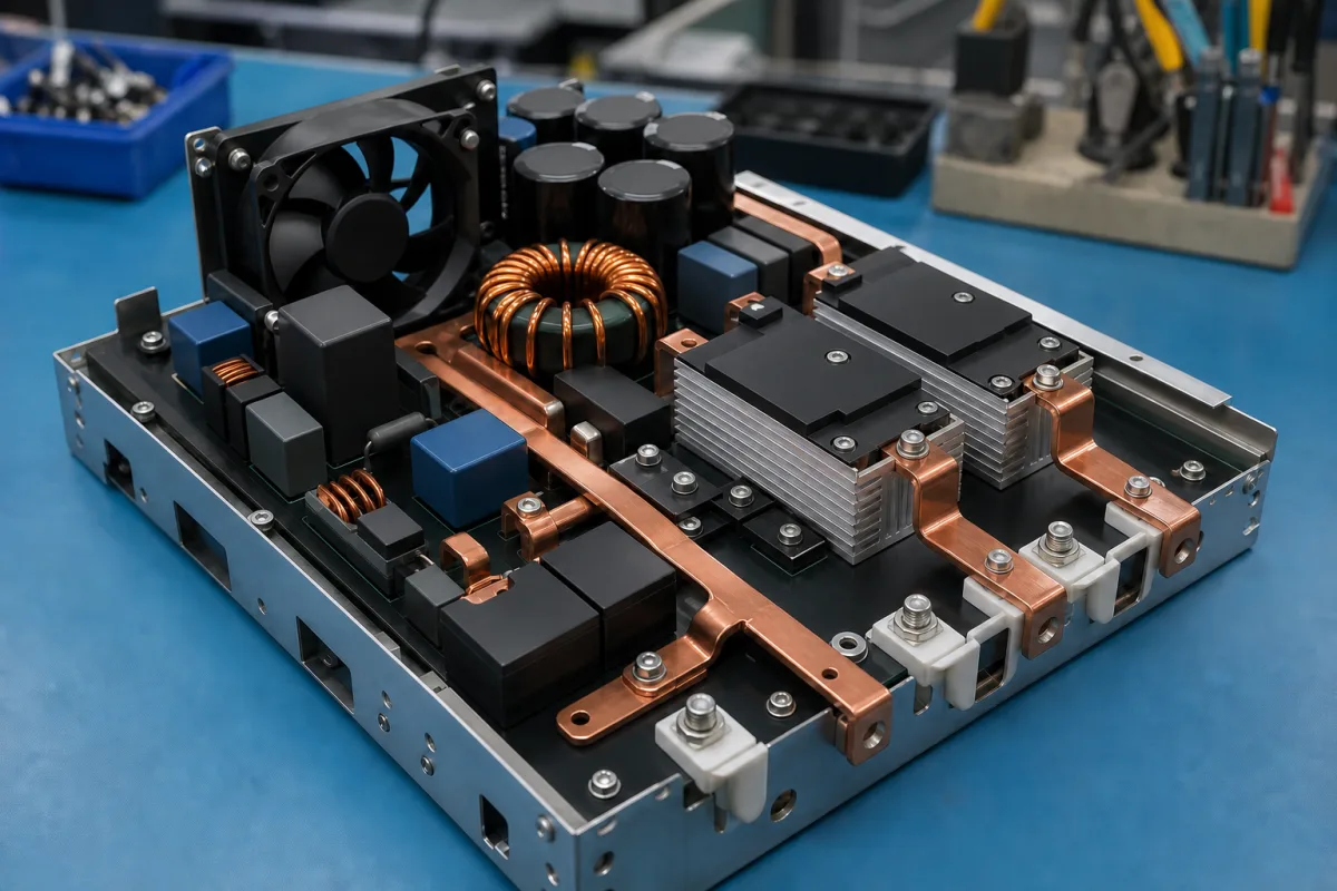
Representative product image. Confirm appearance and specifications with the manufacturer.

Product Specifications

Technical details and manufacturing context for Power Control Module

Definition
The Power Control Module is a specialized electronic component used within a programmable induction cooktop. Its primary function is to regulate and manage the electrical power supplied to the induction coils, enabling precise temperature control, adjustable power levels, and safety operations based on user inputs and sensor feedback. The module receives control signals from the user interface or a microcontroller, processes these inputs, and modulates the power output to the induction coils using semiconductor switching devices such as IGBTs or MOSFETs. This modulation achieves the desired heating effect while continuously monitoring for faults and ensuring safe operation. The module is typically built on a printed circuit board (PCB) with copper traces and includes electronic components such as capacitors, resistors, and inductors. It operates with an input voltage of 220–240 V AC, which is standard for household mains in China and Europe. The output power is adjustable for different cooking zones, ranging from 1000 to 3500 W. The switching frequency is maintained above 20 kHz to avoid audible noise, typically between 20 and 50 kHz. The module achieves an efficiency of at least 90% at rated power, in accordance with IEC 60335-2-6. It is designed to operate within an ambient temperature range of -20 to 85 °C and can be stored in temperatures from -40 to 125 °C. The module is rated for non-condensing relative humidity of 5–95% per IEC 60068-2-78. It offers ingress protection of IP54–IP65 per IEC 60529, providing protection against dust and water jets. The isolation voltage between input and output is 1500 V AC for 1 minute per IEC 60335-1. The power factor is at least 0.95 at full load per IEC 61000-3-2. In standby mode, the module consumes no more than 0.5 W per IEC 62301. Typical dimensions are 150×100×30 mm, and the weight ranges from 150 to 250 g depending on the heatsink and enclosure. These specifications are reference values and must be verified with the legal manufacturer or supplier for the specific model and application.
Working Principle
The Power Control Module receives control signals from the user interface or microcontroller, which specify the desired heating level. It processes these inputs and uses semiconductor switching devices, typically IGBTs or MOSFETs, to modulate the power delivered to the induction coils. By rapidly switching the current on and off at a frequency above 20 kHz, the module controls the average power supplied, achieving the required temperature. The module also monitors for faults such as overcurrent, overvoltage, and overheating, and can shut down or reduce power to ensure safe operation.
Common Materials
Printed Circuit Board (PCB), Semiconductors (IGBTs/MOSFETs), Copper traces, Electronic components (capacitors, resistors, inductors)
Technical Parameters
ParameterTypical rangeNotes & selection driver
Input Voltage220–240 V ACStandard household mains in China and Europe.
Output Power1000–3500 WAdjustable for different cooking zones.
Switching Frequency20–50 kHzAbove 20 kHz to avoid audible noise.
Efficiency≥90 %At rated power.IEC 60335-2-6
Operating Temperature-20–85 °CAmbient temperature range.
Storage Temperature-40–125 °CNon-operating condition.
Relative Humidity5–95 % RHNon-condensing.IEC 60068-2-78
Ingress ProtectionIP54–IP65Protection against dust and water jets.IEC 60529
Isolation Voltage1500 V ACBetween input and output for 1 minute.IEC 60335-1
Power Factor≥0.95At full load.IEC 61000-3-2
Standby Power≤0.5 WIn standby mode.IEC 62301
Dimensions150×100×30 mmTypical module footprint.
Weight150–250 gDepends on heatsink and enclosure.

Ranges are indicative industry figures for RFQ preparation, not a supplier commitment. Confirm every value and standard with the legal manufacturer before ordering.

Components / BOM
  • Power Switching Circuit
    Controls the on/off switching of power to induction coils using semiconductor devices
    Material: Semiconductors (IGBTs/MOSFETs), PCB
  • Control Logic Board
    Processes input signals and generates control signals for power switching
    Material: PCB, microcontrollers, integrated circuits
  • Heat Sink Part
    Dissipates heat generated by power semiconductors during operation
    Material: Aluminum alloy
  • Protection Circuitry
    Monitors for overcurrent, overvoltage, and overtemperature conditions to ensure safe operation
    Material: Electronic components (sensors, comparators, fuses)

Industrial Ecosystem & Supply Chain Structure

Complementary Systems
Downstream Applications
Specialized Tooling

Application Fit & Sizing Matrix

Operational Limits
voltage: 100-240V AC, 50/60Hz
temperature: -20°C to +85°C
power rating: Up to 3.6kW per module
Media Compatibility
✓ Induction cooktop systems ✓ Residential kitchen appliances ✓ Commercial food service equipment
Unsuitable: High-vibration industrial machinery environments
Sizing Data Required
  • Maximum cooktop power requirement (kW)
  • Number of heating zones to control
  • Available electrical supply voltage and phase configuration

Reliability & Engineering Risk Analysis

Failure Mode & Root Cause
Overheating and thermal degradation
Cause: Inadequate cooling, dust accumulation on heat sinks, or prolonged operation at high loads exceeding thermal design limits.
Capacitor failure and power instability
Cause: Electrolytic capacitor aging due to high temperatures, voltage spikes, or manufacturing defects leading to reduced capacitance and increased ESR.
Maintenance Indicators
  • Audible buzzing or arcing sounds from the module indicating loose connections or component breakdown
  • Visible discoloration, bulging, or leaking capacitors on the circuit board
Engineering Tips
  • Implement regular thermal imaging inspections to identify hot spots and ensure cooling systems (fans, heatsinks) remain clean and functional
  • Use voltage stabilizers or surge protectors on input power lines and schedule preventive replacement of electrolytic capacitors before their rated end-of-life

Indicative industry ranges for design and RFQ preparation. Confirm the exact figures and applicable standard with the manufacturer before specifying.

Compliance & Manufacturing Standards

Applicable Standards
IEC 61010-1:2010 - Safety Requirements for Electrical Equipment for Measurement, Control, and Laboratory Use CE Marking - Compliance with EU Directives (e.g., Low Voltage Directive 2014/35/EU)

Quoted from the published standard.

Manufacturing Precision
  • PCB Trace Width: +/-0.05mm
  • Component Placement Accuracy: +/-0.1mm
Quality Inspection
  • In-Circuit Test (ICT) - Electrical Functionality Verification
  • Thermal Cycling Test - Reliability Under Temperature Stress

Manufacturers of Power Control Module

Manufacturer profiles associated with Power Control Module.

Sourcing Power Control Module from China?
Tell us your specification and target quantity — we will match it against manufacturer records and come back with the factories that fit.
Request manufacturers We manufacture this

Manufacturer listings support early research and capability understanding. They are not certification, ranking, or transaction guarantees.

Technical documentation
Request current drawings, revision history, and a signed specification sheet.
Manufacturing capability
Verify equipment lists, process limits, capacity, and representative production evidence.
Inspection readiness
Confirm test methods, calibrated equipment, sampling plans, and traceable reports.
Supplier transparency
Check the legal entity, factory address, ownership, certifications, and direct contacts.

CNFX does not score or rank suppliers. Buyers must verify all claims and documents with the legal manufacturer before ordering.

Supply Chain Compatible Machinery & Devices

Medium Voltage Switchgear Assembly Line

Automated production system for assembling medium voltage electrical switchgear.

Explore Specs →
Motor Terminal Block

A motor terminal block is a standardized electrical component that provides secure, insulated connection points for motor winding leads.

Explore Specs →
PLC Control System

A digital industrial computer control system that monitors inputs, makes decisions based on a custom program, and controls outputs to automate industrial processes.

Explore Specs →
Control Panel

A centralized interface for monitoring and controlling industrial equipment and processes

Explore Specs →

Frequently Asked Questions

What is the function of the Power Control Module in an induction cooktop?

The Power Control Module regulates the electrical power supplied to the induction coils, enabling precise temperature control, adjustable power levels, and safety functions based on user input and sensor feedback.

What are the typical input voltage and output power ranges?

The module operates with an input voltage of 220–240 V AC, which is standard for household mains in China and Europe. The output power is adjustable from 1000 to 3500 W, depending on the cooking zone.

Which standards are referenced for the module's performance?

The module references standards such as IEC 60335-2-6 for efficiency, IEC 60068-2-78 for humidity, IEC 60529 for ingress protection, IEC 60335-1 for isolation voltage, IEC 61000-3-2 for power factor, and IEC 62301 for standby power. These are verification references and do not imply certification.

How should I verify the specifications for a specific model?

The listed parameters are reference ranges. For a specific model, you must contact the legal manufacturer or supplier to confirm exact values, standards compliance, and suitability for your application.

Data Basis

Editorial classification, named public sources where available, and source-reviewed manufacturer records.

Preliminary Technical Classification
This page supports structured research, RFQ preparation, and supplier evaluation. It does not replace buyer-led supplier qualification, standards review, or technical approval.
Buyer enquiry

Request manufacturing insight for Power Control Module

Ask for use case, specification boundaries, supplier type, and RFQ preparation information for this product.

Where it goes
Straight to the CNFX editorial desk, and to the manufacturer if this product is linked to a claimed profile. Nothing is broadcast to a supplier list.
Your details stay here
We do not sell or rent enquiry data, and we do not add you to a mailing list. Used only to answer this request.
No commission, no middleman
CNFX is a directory. We take no cut of any order and never negotiate on a supplier's behalf.
What we don't claim
A listing is not an endorsement. Qualify every supplier and verify every figure yourself before ordering.

Your business information is used only to process this request.

Thank you! Your message has been sent. We'll respond within 1–3 business days.
Sorry, we couldn't send your message. Please try again, or email us at contact@cnfx.com.

Need to Manufacture Power Control Module?

Compare manufacturer profiles with relevant product and process capability.

Previous Product
Wire Tensioning System
Last Product
Get QuotesChat