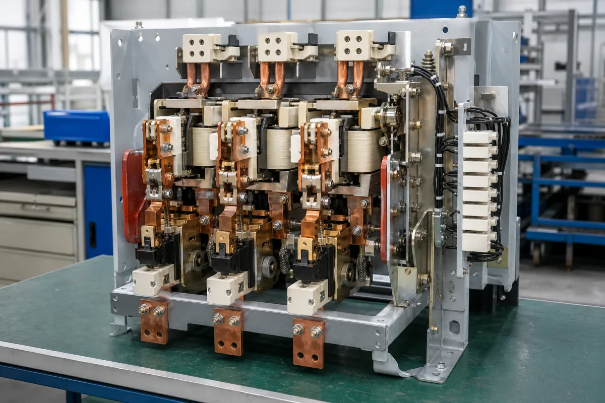
Open-frame power contactor assembly for crane and mill duty: single-pole units tied into multi-pole sets, rated by NEMA size and duty
Heavy open-frame contactors built up from single-pole units on a steel panel for crane, mill and traction-type duty · NEMA sizes 1 to 8 from 25 A to 1,350 A open 8-hour rating, tie bars and series half-voltage coils for multi-pole sets, and arc chutes, blowout coils and tip materials for hard service
On crane and mill control panels, where one electric arc furnace charging crane can make 690,000 moves a year, power contactors are built as open assemblies rather than moulded blocks: each pole is its own unit with a hinged arc shield and replaceable tips, mounted on an insulating base or a steel pan, and two or three poles are tied mechanically to act as one. The North American lines are chosen by NEMA size, open or enclosed rating and duty; the large open-design European ranges by IEC utilisation category and current.
Open-frame heavy-duty power contactors and contactor assemblies for crane, steel-mill, magnet and similar hard-service control: single-pole AC and DC contactors on insulating bases or steel panels, tie-bar multi-pole sets, reversing pairs with mechanical interlocks, and open-design large-frame contactors with blowout coils and arc chutes. Block-type low-voltage AC contactors for motors and main circuits, selected by IEC utilisation category, are covered on the Power contactor page; contactors for capacitor bank switching on their own page; vacuum contactors are outside this page.
CNFX editorial research · Sources checked October 12, 2026 · 4 sources
NEMA size 1 to 8: 25 A to 1,350 A open, about 10 % less enclosed, a third more for intermittent duty
Hubbell Industrial Controls' Type 5110 crane and mill-duty AC magnetic contactor, for AC cranes, steel mills, magnet controllers and as line or dynamic-braking contactors for drives, is rated for 600 V AC at 40 °C ambient: [1]
Editorial calculation from the table: the enclosed rating is 90 % of the open rating from size 2 up (92 % at size 1), and the intermittent rating is about 1.33 times the open 8-hour rating. EC&M's Type M single-pole line covers the same NEMA range: the Class 7004 DC contactor, normally open or normally closed, sizes 1 to 8 up to 600 V DC, 25 A to 1,350 A open 8-hour; the Class 8503 AC contactor, normally open, sizes 2 to 8 up to 600 V AC, 50 A to 1,350 A. [2]
The 5110's operating coils are built to NEMA standards to withstand 110 % of rated voltage continuously and to operate the contactor at 80 %; standard coil voltages are 115 V DC and 230 V DC. [1] EC&M quotes a 25-year life for a maintained contactor crane control and 690,000 moves a year for an electric arc furnace charging crane, giving about 17 million moves; its crane panels are rated to 40 °C, with high-temperature panels and derated devices to 60 °C. [3]
State the motor current, whether the contactor sits in an open panel or an enclosure, and whether the duty is continuous or intermittent, so the NEMA size is read from the right column.
02
Multi-pole sets from single poles: tie bars, half-voltage coils in series and interlocked reversing pairs
Above size 2 these contactors are built one pole at a time. Hubbell's 5110 offers sizes 1 and 2 with one, two or three poles; for sizes 3 to 8 a two-pole normally open contactor is made from two single-pole contactors with half-voltage operating coils and one tie bar kit, the two coils wired in series. [1]
A reversing contactor is two single-pole or two double-pole units mounted side by side with a horizontal mechanical interlock; Hubbell's reversers include both mechanical and electrical interlocks. Auxiliary contact blocks, bridge-type double-break silver-cadmium oxide, mount on either side and can be stacked two deep. [1] EC&M likewise sells tie bar kits that join AC or DC single-pole Type M contactors into multi-pole contactors, a mechanical interlock for normally open units, and electrical interlocks; its Type M mounts on a high-strength insulating base for steel panel mounting, with power terminations on both sides and all parts accessible from the front. [2]
ABB's R contactors take the opposite approach for very large currents: all poles, the electromagnet and auxiliary contacts sit on one main frame with a fixed bar and a rotating shaft on two bearings, a small frame for R63 to R500 and a large frame for R800 to R5100. They are offered 3- or 4-pole for AC and 1-, 2- or 3-pole for DC, with normally open, normally closed or mixed main poles. [4]
For a tied set, specify the number of poles, the coil voltage per pole (half-voltage coils in series for two poles), reversing interlocks, and auxiliary contacts per side.
03
Arc chutes, blowout coils and contact tips for hard service
These contactors interrupt motor currents in dusty, vibrating plant, so arc handling and tip renewal are built into the design:
ABB attributes the higher ratings of its R range to the open design, which dissipates heat better, and feeds the coil through a rectifier bridge for buzz-free operation, with a 120 V 60 Hz coil and 2 NO + 2 NC auxiliary contacts as standard. [4] EC&M recommends silver-faced tips for contactors that remain closed for extended periods, the same advice Hubbell gives for manual-magnetic disconnect switches. [2][1]
Feature
What the maker states
Arc interruption, EC&M Type M
Line-Arc principle developed by EC&M in the 1930s; arc chute pivots upward for tip inspection; surfaces arranged to avoid accumulating conductive dust [2]
Arc interruption, ABB R
Blowout coil rated to carry the total current flowing through the poles; arcing horn; arc chutes removable for contact inspection [4]
Contact tips, Hubbell 5110
Copper standard; silver-faced for contactors closed for long periods; silver-tungsten-carbide for hard service; renewal kits with an arc horn in sizes 6 to 8 [1]
Ratings range, ABB R
63 A to 5,000 A; up to 1,000 V AC or 1,500 V DC; AC-1, AC-3, DC-1, DC-3 and DC-5; UL general use 800 to 2,000 A at 600 V DC [4]
Endurance, ABB R
Up to 5 million electrical operations; mechanical switching frequency up to 1,200 cycles per hour [4]
Name the tip material wanted for the duty, spare arc chutes and tip kits per size, and whether the contactor will stay closed for long periods.
04
What to send when ordering an open-frame mill-duty contactor assembly
Paste it into your enquiry below or into an email to a maker, then replace every bracket.
Duty: [crane hoist / travel / mill auxiliary / magnet / drive line contactor]
Circuit: [AC or DC; voltage; motor kW or HP; full-load current]
Rating basis: [open or enclosed; 8-hour or intermittent; NEMA size]
Poles: [number; NO/NC; tied single poles; reversing pair]
Coil: [voltage AC/DC; series half-voltage coils]
Contacts: [copper / silver-faced / silver-tungsten-carbide; auxiliaries]
Mounting: [steel panel; insulating base; ambient up to 40 or 60 °C]
Explore company information and manufacturing capabilities, then discuss the scope of your project with a relevant supplier.
Share this page
Compiled and source-reviewed by the CNFX editorial team.
Each manufacturer above links to the page on that company's own website where the product is listed, with the date we checked it. How we source and review
· Page last updated 13 October 2026
Buyer questions
What current does each NEMA size carry on a mill-duty contactor?
On Hubbell's 5110 at 600 V AC, open 8-hour ratings run from 25 A at size 1 to 1,350 A at size 8, with intermittent ratings of 33 A to 1,800 A. [1]
How are multi-pole mill-duty contactors built?
From single-pole units joined by a tie bar kit; Hubbell uses two half-voltage coils wired in series for a two-pole set from size 3 up. [1][2]
Which contact tips suit a contactor that stays closed for long periods?
Silver-faced tips, according to both Hubbell and EC&M; copper is standard and silver-tungsten-carbide is offered for hard service. [1][2]
How large do open-design contactors go?
ABB's R contactors range from 63 A to 5,000 A, up to 1,000 V AC or 1,500 V DC. [4]
Sources and what still needs a direct check
Sources checked 2026-10-12. NEMA size ratings, coils and multi-pole construction come from Hubbell Industrial Controls' 5110 catalogue; single-pole Type M ranges and crane duty figures from EC&M brochures; large open-design contactors from ABB's R contactor brochure.