Portable and fixed power quality analysers · IEC 61000-4-30 Class A measurement methods and uncertainty, aggregation intervals, dip and swell detection, harmonics and flicker references, time synchronisation, and what a Class A data sheet should state
A power quality analyser measures and records the quality of an electrical supply: voltage and frequency, dips, swells and interruptions, unbalance, harmonics, flicker and current. Class A instruments under IEC 61000-4-30 follow defined methods so results from different instruments can be compared. Ask three things first: which parameters and class you need and why, whether the stated uncertainty holds over your voltage range, and how data are time-stamped, aggregated and exported.
Portable and permanently installed power quality analysers and recorders for low- and medium-voltage networks (through voltage and current transformers), including Class A instruments and their current clamps and software. Simple multimeters (see portable digital multimeter), energy meters (see energy meter), power factor correction equipment and transient recorders are outside this page except where compared.
CNFX editorial research · Sources checked October 11, 2026 · 4 sources
Fluke's application note on IEC 61000-4-30 Class A states that the standard defines measurement methods, time aggregation, accuracy and evaluation for each power quality parameter so results are reliable, repeatable and comparable, and that IEC 62586 sets the minimum parameters and IEC 62586-2 the functional test and uncertainty requirements for Class A instruments; the standard dates from 2003 and was at Edition 3 (2015). Class A requires a supply voltage measurement uncertainty of 0.1% of the declared input voltage over 10% to 150% of it, contiguous non-overlapping measurement over 10/12-cycle intervals at 50/60 Hz, and covers frequency, voltage magnitude, flicker (IEC 61000-4-15), dips, swells and interruptions, unbalance, voltage and current harmonics and interharmonics (IEC 61000-4-7), mains signalling, rapid voltage changes and current magnitude. [1]
Dips, swells and interruptions must be measured on a full cycle and updated every half cycle. Data must be aggregated in 10/12-cycle (about 200 ms), 150/180-cycle (about 3 s), 10-minute (synchronised to UTC) and 2-hour (long-term flicker) intervals, and time stamps must be accurate to ±20 ms at 50 Hz or ±16.7 ms at 60 Hz, which needs GPS or NTP synchronisation; without it the tolerance should be better than ±1 s per 24 h. The note warns that "in many cases only the accuracy at full scale is specified" and that "low cost power quality measurement systems often have higher uncertainty levels when measuring at the lower end of the scale", for example when measuring 58 V phase to neutral on a potential transformer. [1]
Editorial calculation: 0.1% of a 230 V declared input is ±0.23 V, and the same 0.1% applied to a 58 V input is ±0.058 V; ask the supplier to state uncertainty at the voltage you will actually measure. [1]
Give the supplier the networks to be measured (voltage levels, single or three phase, through VTs or CTs), parameters needed, required class and the edition of IEC 61000-4-30, current ranges and clamp types, recording duration and memory, time synchronisation (GPS or NTP), communications and software, measurement category and safety rating needed at your connection points, power supply and battery life, and calibration certificates.
02
Set inputs, ranges and data handling
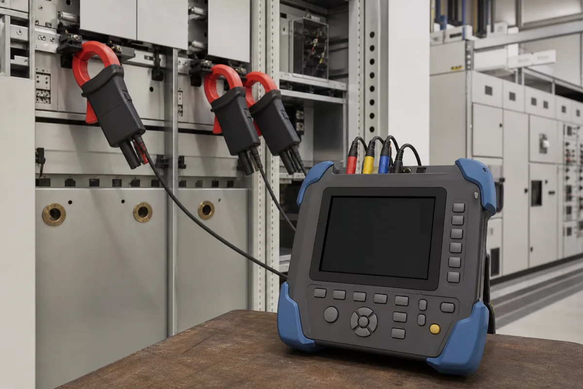
As an example of a Class A instrument, one maker's brochure for a portable three-phase analyser states full compliance with IEC 61000-4-30 Class A, a 5 V to 1000 V three-phase range for single- and three-phase networks, five voltage and four current input terminals, a 7-inch colour touch screen, recording to a removable SD card with transfer by software or USB, and measurement time accuracy better than ±0.3 s per day. [2]
Editorial note: ask the supplier for its IEC 62586-2 test report or other evidence of Class A conformance, the uncertainty at your voltage and current, and the clamp accuracy, since the system accuracy depends on clamps and transformers as well as the instrument.
Metrel's product page for its MI 2893 Power Master XT, a hand-held three-phase analyser it lists as compliant with IEC 61000-4-30 Ed. 3.0 Class A, gives four voltage and four current channels with automatic clamp recognition, transient recording at more than 1 MSamples/s on 8 channels simultaneously, harmonic and interharmonic analysis up to the 50th harmonic with THD and TDD, power to IEEE 1459, variable-frequency-drive measurement at 5–120 Hz and 400 Hz systems, up to 7 adjustable alarms, a supplied 8 GB microSD card (up to 32 GB supported), Ethernet communication and optional GPS clock synchronisation, in a 230 × 140 × 80 mm, 1.1 kg housing. Its advanced and Euro sets include four 1-phase flexible clamps with 3000 / 300 / 30 A ranges. [4]
Editorial calculation: Metrel's transient sampling of more than 1 MSamples/s compares with the 2 MHz HIOKI lists for its PQ3198, and its 1.1 kg against HIOKI's 2.6 kg; both reach the 50th harmonic. Where you need supraharmonics, VFD outputs or an optional GPS clock, list them in the enquiry, since these are maker options beyond the Class A methods. [4][3]
03
Add the clamp error to the current accuracy before you compare
HIOKI's specification page for its PQ3198, an analyser it states complies with IEC 61000-4-30 Ed. 3 Class A, shows how current and power accuracy depend on the sensor. Voltage accuracy is ±0.1% of nominal voltage, but current is ±0.1 % rdg. ±0.1 % f.s. + current sensor accuracy, and active power ±0.2 % rdg. ±0.1 % f.s. + current sensor accuracy, with accuracy guaranteed for 1 year. [3] The sensors listed for it carry their own figures: AC flexible sensors rated 600A or 6000A AC at ±1.5% from 10 Hz to 50 kHz, and AC/DC auto-zero sensors at ±1.0% (100A), ±2.0% (600A) and ±1.5% (2000A) from DC to 5 kHz. [3]
The same page lists capabilities beyond the Class A minimum that a buyer may need to specify separately: transient capture to 6.0000 kV peak with 2 MHz sampling, high-order harmonic (supraharmonic) components from 2 kHz to 80 kHz, harmonics from the 0th to 50th order and interharmonics from 0.5th to 49.5th, recording for 1 year with up to 9999 events per day, an optional GPS box to correct the clock to UTC, and a battery pack rated for 180 minutes of continuous use in a 2.6 kg instrument. [3]
Editorial calculation: at a reading equal to full scale with a ±1.5% flexible sensor, the stated terms add to 0.1% + 0.1% + 1.5% = 1.7% for current, against 0.1% for voltage, so ask suppliers to quote current and power accuracy with the clamp you will buy. [3]
04
Class, voltage and current inputs, aggregation intervals, time sync and storage
Aggregation and time sync are fixed by the Class A method (200 ms, 3 s, 10 min and 2 h intervals; ±20 ms at 50 Hz), while input ranges, clamps and storage differ from one instrument to the next. [1][2]
Voltage range and accuracy, clamp-dependent current accuracy, harmonics and storage for a PQ analyser order
Voltage accuracy is the one row set by Class A (0.1% of Udin over 10–150%); current accuracy is the instrument plus its clamp, and frequency range, temperature, humidity, ingress protection, power supply and battery life are left for the supplier to state. [1]
1 company lists this product among what they make. Company figures are quoted from each
company's own website; every card states where the relationship came from.
Acrel Co., Ltd.
Manufacturing site to be confirmed for the order
Lists the APView series power quality analyser for substations, PV, energy storage and grid-connection points.
Explore company information and manufacturing capabilities, then discuss the scope of your project with a relevant supplier.
Share this page
Compiled and source-reviewed by the CNFX editorial team.
Each manufacturer above links to the page on that company's own website where the product is listed, with the date we checked it. How we source and review
· Page last updated 13 October 2026
Buyer questions
What does IEC 61000-4-30 Class A require for voltage accuracy?
Measurement uncertainty of 0.1% of declared input voltage over 10% to 150% of that voltage (Fluke application note). [1]
How are dips and swells measured in Class A?
On a full-cycle RMS value updated every half cycle. [1]
Why does time synchronisation matter?
Class A needs ±20 ms (50 Hz) time stamps, via GPS or NTP, so events can be correlated across instruments. [1]
Does a Class A analyser's accuracy include the current clamps?
Not in HIOKI's PQ3198 specification: current and power accuracy are stated as the instrument figure plus current sensor accuracy, and its listed sensors range from ±1.0% to ±2.0%. [3]
How many channels does a portable Class A analyser have?
Metrel lists four voltage and four current channels for its MI 2893, with transients sampled at more than 1 MSamples/s on all 8 channels. [4]
Sources and what still needs a direct check
Sources checked 2026-10-11. All four sources are instrument makers' publications — Fluke's application note explaining IEC 61000-4-30 Class A, an AEMC brochure, and HIOKI and Metrel product specification pages — cited as examples, not endorsements. The IEC standards themselves are not reproduced.