Editorial Technical Reference

Robotic Routing Arm

This page explains how Robotic Routing Arm is classified within Electrical Equipment Manufacturing. Technical values and manufacturer relationships are research references; confirm the current specification and supplier evidence for each order.

Technical Definition & Core Assembly

A robotic arm component within an automatic wiring system that precisely routes and positions electrical wires or cables.
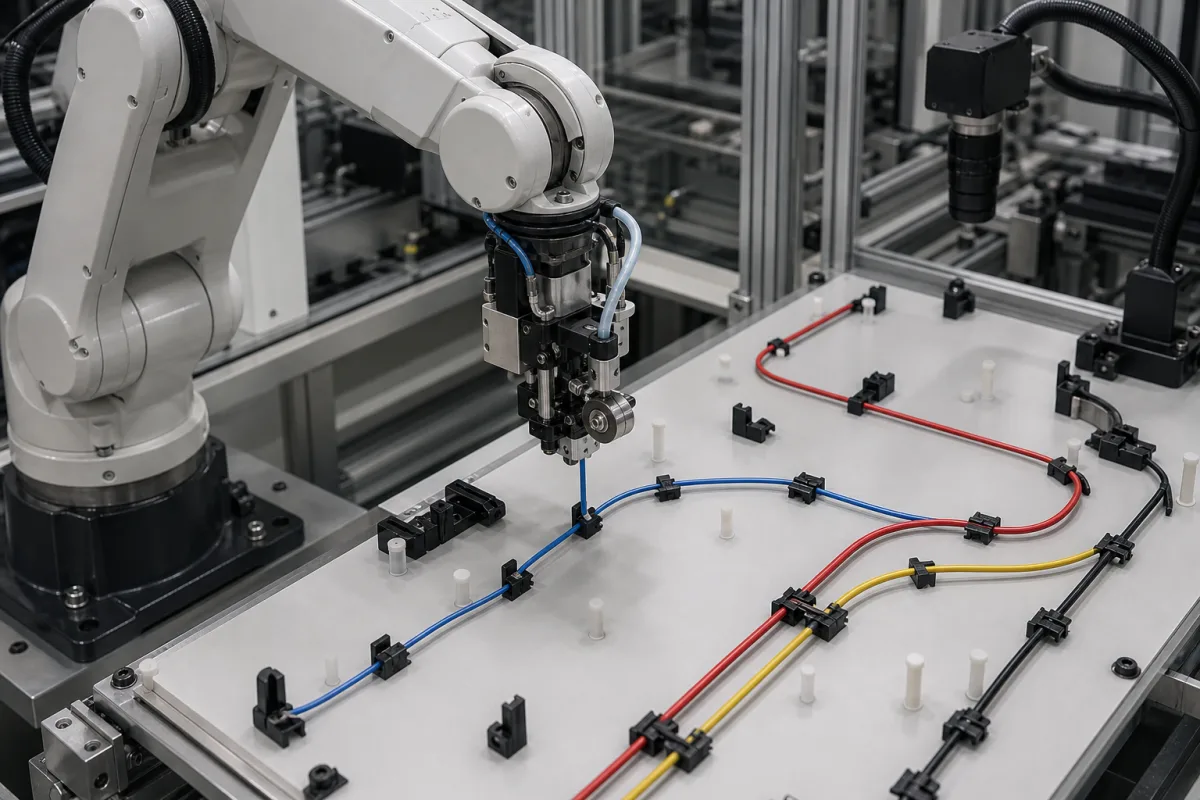
Representative product image. Confirm appearance and specifications with the manufacturer.

Product Specifications

Technical details and manufacturing context for Robotic Routing Arm

Definition
The Robotic Routing Arm is a specialized robotic component of an Automatic Wiring System designed to automate the precise routing, positioning, and laying of electrical wires, cables, or harnesses. It operates within a defined workspace to follow programmed paths, ensuring accurate wire placement for assembly in electrical equipment manufacturing. The arm receives digital instructions (e.g., CAD/CAM data) from the system controller. Servo motors or actuators move the arm's joints to position its end-effector (e.g., gripper, guide nozzle) along a pre-defined 3D path. It may integrate sensors for real-time positioning feedback, enabling precise routing of wires through fixtures, clips, or channels to their termination points. Typical specifications include 4–6 axes, a maximum reach of 600–1500 mm, payload capacity of 2–10 kg, repeatability of ±0.05–±0.1 mm (per ISO 9283), maximum speed of 1–3 m/s, operating temperature of -10–50 °C, degree of protection IP54–IP65 (per IEC 60529), supply voltage 24 V DC ±10%, power consumption 0.5–2.0 kW, weight 30–120 kg, and mounting positions floor, wall, or ceiling. Communication interfaces include EtherCAT and PROFINET (per IEC 61158). Materials commonly used include aluminum alloy, steel, and engineering plastics. These values are reference ranges; verify model-specific specifications with the manufacturer or supplier.
Working Principle
The arm receives digital instructions (e.g., CAD/CAM data) from the system controller. Servo motors or actuators move the arm's joints to position its end-effector (e.g., gripper, guide nozzle) along a pre-defined 3D path. It may integrate sensors for real-time positioning feedback, enabling precise routing of wires through fixtures, clips, or channels to their termination points.
Common Materials
Aluminum alloy, Steel, Engineering plastics
Technical Parameters
ParameterTypical rangeNotes & selection driver
Number of Axes4–6Determines reachable workspace and flexibility
Maximum Reach600–1500 mmDefines the envelope for wire routing
Payload Capacity2–10 kgIncludes end-effector and wire bundle weight
Repeatability±0.05–±0.1 mmCritical for precise wire placementISO 9283
Maximum Speed1–3 m/sAffects cycle time and throughput
Operating Temperature-10–50 °COutside this range, lubricants and electronics may fail
Degree of ProtectionIP54–IP65IP65 for dusty or wet environmentsIEC 60529
Supply Voltage24 ±10% V DCCommon for industrial automation
Power Consumption0.5–2.0 kWDepends on axis count and speed
Weight30–120 kgAffects mounting structure and portability
Mounting PositionFloor, wall, ceilingFlexibility for integration into wiring lines
Communication InterfaceEtherCAT, PROFINETFor integration with PLC and higher-level systemsIEC 61158

Ranges are indicative industry figures for RFQ preparation, not a supplier commitment. Confirm every value and standard with the legal manufacturer before ordering.

Components / BOM
  • Arm Structure Part
    Provides the mechanical framework and reach for the routing operations
    Material: Aluminum alloy or steel
  • End-Effector/Gripper
    Holds, guides, or releases the wire/cable during routing
    Material: Engineering plastics or composite
  • Servo Motors/Actuators
    Drive the movement of arm joints with precision
    Material: Metal, copper windings
  • Control Interface
    Connects to the main system controller for receiving routing instructions
    Material: Electronic components, plastics
  • Position Sensors Optional
    Give the controller real-time arm pose so the routed path can be corrected, on instrumented arms.

Applied To / Applications

This component is essential for the following industrial systems and equipment:

Industrial Ecosystem & Supply Chain Structure

Complementary Systems
Downstream Applications
Specialized Tooling

Application Fit & Sizing Matrix

Operational Limits
pressure: Atmospheric to 1.5 bar (typical wiring environment)
other spec: Positioning accuracy: ±0.1 mm, Repeatability: ±0.05 mm, Max wire diameter: 25 mm, Max routing speed: 2 m/s
temperature: 0°C to 50°C (operational), -20°C to 70°C (storage)
Media Compatibility
✓ PVC insulated wires ✓ Teflon/PTFE cables ✓ Shielded industrial control cables
Unsuitable: Explosive atmospheres (ATEX Zone 0/1) without additional certification
Sizing Data Required
  • Maximum wire bundle diameter (mm)
  • Required workspace envelope dimensions (L×W×H in mm)
  • Number of routing axes/degrees of freedom needed

Reliability & Engineering Risk Analysis

Failure Mode & Root Cause
Joint bearing wear
Cause: Inadequate lubrication leading to metal-on-metal contact, accelerated by particulate contamination and misalignment
Encoder signal degradation
Cause: Electrical noise interference, cable fatigue from repetitive motion, and moisture ingress compromising signal integrity
Maintenance Indicators
  • Unusual grinding or clicking sounds during articulation
  • Visible position drift or overshoot during programmed movements
Engineering Tips
  • Implement condition-based lubrication using automated grease systems with particle filtration to maintain optimal bearing surfaces
  • Install shielded cable management with strain relief and regular IR thermography scans to detect early electrical/mechanical degradation

Indicative industry ranges for design and RFQ preparation. Confirm the exact figures and applicable standard with the manufacturer before specifying.

Compliance & Manufacturing Standards

Applicable Standards
ISO 9283:1998 - Manipulating industrial robots - Performance criteria and related test methods ANSI/RIA R15.06 - Industrial Robots and Robot Systems - Safety Requirements CE Marking - Compliance with EU Machinery Directive 2006/42/EC for safety and health requirements

Quoted from the published standard.

Manufacturing Precision
  • Positional repeatability: +/-0.05mm
  • Load capacity deviation: +/-1.5% of rated capacity
Quality Inspection
  • Laser interferometer accuracy test for positioning and repeatability
  • Functional safety test per ISO 13849-1 for control system reliability

Manufacturers of Robotic Routing Arm

Manufacturer profiles associated with Robotic Routing Arm.

Sourcing Robotic Routing Arm from China?
Tell us your specification and target quantity — we will match it against manufacturer records and come back with the factories that fit.
Request manufacturers We manufacture this

Manufacturer listings support early research and capability understanding. They are not certification, ranking, or transaction guarantees.

Technical documentation
Request current drawings, revision history, and a signed specification sheet.
Manufacturing capability
Verify equipment lists, process limits, capacity, and representative production evidence.
Inspection readiness
Confirm test methods, calibrated equipment, sampling plans, and traceable reports.
Supplier transparency
Check the legal entity, factory address, ownership, certifications, and direct contacts.

CNFX does not score or rank suppliers. Buyers must verify all claims and documents with the legal manufacturer before ordering.

Supply Chain Compatible Machinery & Devices

Motor Terminal Block

A motor terminal block is a standardized electrical component that provides secure, insulated connection points for motor winding leads.

Explore Specs →
PLC Control System

A digital industrial computer control system that monitors inputs, makes decisions based on a custom program, and controls outputs to automate industrial processes.

Explore Specs →
Control Panel

A centralized interface for monitoring and controlling industrial equipment and processes

Explore Specs →
PLC Control Panel

A centralized interface unit housing the programmable logic controller and associated control components for industrial automation systems.

Explore Specs →

Frequently Asked Questions

What is the typical number of axes for a Robotic Routing Arm?

The typical number of axes ranges from 4 to 6, which determines the reachable workspace and flexibility. Verify the exact number for your specific model.

What is the maximum reach of the Robotic Routing Arm?

The maximum reach is typically between 600 and 1500 mm, defining the envelope for wire routing. Confirm the exact reach for your application.

What repeatability can be expected?

Repeatability is typically ±0.05 to ±0.1 mm, per ISO 9283, which is critical for precise wire placement. Always verify with the manufacturer.

What communication interfaces are supported?

Common interfaces include EtherCAT and PROFINET, per IEC 61158, for integration with PLC and higher-level systems. Check compatibility with your control system.

Data Basis

Editorial classification, named public sources where available, and source-reviewed manufacturer records.

Preliminary Technical Classification
This page supports structured research, RFQ preparation, and supplier evaluation. It does not replace buyer-led supplier qualification, standards review, or technical approval.
Buyer enquiry

Request manufacturing insight for Robotic Routing Arm

Ask for use case, specification boundaries, supplier type, and RFQ preparation information for this product.

Where it goes
Straight to the CNFX editorial desk, and to the manufacturer if this product is linked to a claimed profile. Nothing is broadcast to a supplier list.
Your details stay here
We do not sell or rent enquiry data, and we do not add you to a mailing list. Used only to answer this request.
No commission, no middleman
CNFX is a directory. We take no cut of any order and never negotiate on a supplier's behalf.
What we don't claim
A listing is not an endorsement. Qualify every supplier and verify every figure yourself before ordering.

Your business information is used only to process this request.

Thank you! Your message has been sent. We'll respond within 1–3 business days.
Sorry, we couldn't send your message. Please try again, or email us at contact@cnfx.com.

Need to Manufacture Robotic Routing Arm?

Compare manufacturer profiles with relevant product and process capability.

Previous Product
Wire Tensioning System
Last Product
Get QuotesChat