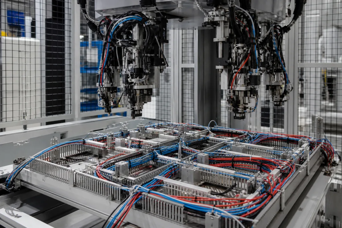
Automatic wiring system for control cabinets and switchgear: robots that route prepared wires through the duct and land them on terminals
Robotic wiring of control-cabinet and switchgear mounting plates · 40 s against 180 s by hand, under 45 s per conductor, 16-wire changers, 0.5–2.5 mm² conductors and a gripper narrow enough for adjacent terminals
Wiring the devices on a mounting plate is the step of control-cabinet building that has stayed manual longest: each wire is cut, stripped, fitted with a ferrule, laid in the duct and screwed or pushed into a terminal at each end. Automatic wiring systems take over some or all of that sequence on the plate itself. This page compares two published systems that divide the work differently, looks at the gripper problem of reaching terminals packed side by side, and sets out what data and layout the robot needs.
Robotic wiring systems for control-cabinet and switchgear mounting plates, mounting frames and DIN-rail assemblies: wire preparation and changing inside the system, routing through the cable duct, connection to screw and push-in terminals, and the checks and data that drive them. Cut-strip-crimp machines that make loose terminated wires for harnesses are covered on the Automated wire harness crimping machine page, cut-strip-twist-tin machines on the Automated wire stripping and termination machine page, and crimp force monitors on the Force monitoring system for crimping and pressing page. The parts being wired have their own pages (Slotted wiring duct for control panels, Terminal block); harness boards, enclosure machining and the cabinets themselves are outside this page.
CNFX editorial research · Sources checked October 12, 2026 · 3 sources
Both ends and the duct, or one end only: how Averex and the WAGO robot divide the work with the operator
The two systems with published data draw the line between robot and operator in different places, and their speed figures are stated on different bases.
Editorial calculation: 15 hours over 300 wires is 180 s per wire, the same as the manual time Kiesling gives, which suggests the 180 s and 40 s figures are per wire. On that reading the saving would be 140 s per wire, or about 11.7 h for 300 wires, not 15 h; ask the supplier for the basis of both numbers.
Editorial calculation: at WAGO's upper bound of 45 s per conductor, connecting one side of 300 conductors takes 3.75 h of robot time, before the operator routes them and lands the second ends.
The W. Althaus AG patent, filed in 2019, describes complete cabinet-wiring robots of the Averex type as error-prone and complex to build and run because of their complexity, and earlier pointer-based assistance devices as taking over only one step while the main load stays with the operator. [3]
Kiesling Averex (announced 2014)
WAGO Cabinet Wiring Robot (2025)
What the machine does
Cuts, strips and fits ferrules, feeds the wire through the cable duct and attaches it to terminal blocks, contactors and motor circuit breakers [1]
Prepares conductors in a separate station; the robot connects one side of each conductor; routing and the second side stay with the operator [2]
Published speed
About 40 s for a wiring process that takes about 180 s by hand on average [1]
State which steps the robot is expected to take (preparation, first end, routing, second end) and ask for the published cycle time on that same basis.
02
0.5 to 2.5 mm², 300 to 2,500 mm, and a pull test before and after the wire is landed
WAGO publishes the conductor envelope of its preparation station and the checks applied to each wire. [2]
Averex also checks before wiring: it uses data from Eplan and component positions from the 3D model to inspect the manually assembled plate, using lasers to identify parts and check their dimensions against assembly tolerances. [1]
Wires the WAGO robot does not handle are pre-assembled and placed in a receptacle for manual use, and the second end of each robot-wired conductor is pre-assembled for the operator. [2]
Pull-out test on each screw connection; force-torque monitoring on spring connections [2]
Check before each job
Camera and laser comparison of target and actual component placement; the wiring path is adjusted from the order data if deviations are found [2]
Give the cross-section and length range of the cabinet's wires, ferrule types, marking or printing needed, and the share of wires outside the robot's range.
03
A jaw 5–20 mm long and an application face under 50 mm²: a gripper for terminals packed side by side
W. Althaus AG's application WO2020038912A1 (priority 22 August 2018) starts from the problem that earlier grippers were too wide to wire connection points next to each other without disturbing wires already landed. [3]
One earlier design placed the pivot axis in the middle of the gripper, which forced the rotation mechanism to the level of the application side and made the gripper wide; another was narrow but could not reach connection points perpendicular to the mounting plate. [3] In the Althaus design the strand is fed to a gripper that moves in the robot head between an insertion position and a re-gripping position, so that the start and the end of the same strand protrude from one application side when they are landed. [3]
The patent gives preferred dimensions for that gripper: a jaw clamping profile 5.0–20.0 mm long, particularly 7.0–12.0 mm; strands of 0.5–10 mm outside diameter, preferably 1–6 mm and particularly 2–4 mm; and an application-side base area below 50 mm², particularly below 35 mm² and very particularly below 25 mm². [3]
Editorial calculation: a square application face of 25 mm² measures 5 mm × 5 mm, and one of 50 mm² about 7.1 mm × 7.1 mm. Compare that with the terminal pitch and the device spacing on the plate when assessing whether a gripper can reach every connection point.
Send the terminal pitch of the densest rail, the connection directions (front, perpendicular to plate) and the outside diameter of the largest and smallest wire.
04
750 mm of reach across a 1,800 mm × 750 mm plate: layout, ducts and the data the robot reads
WAGO gives the robot's wiring area as up to 750 mm wide, enough for up to three fields in a distribution cabinet. For control-cabinet work WAGO writes that the mounting plate "often provides ample space — typically 1,800 mm × 750 mm", and notes that densely packed components or pre-installed ducts can limit the working area; installing ducts after wiring, or wiring pre-assembled DIN rails fed on a rail carriage and mounting them afterwards, are the remedies it describes. [2]
The two systems differ in the data they need. Averex takes Eplan data and the 3D component layout over a machine-to-machine interface. [1] WAGO states that no 3D CAE engineering is required and that cable lists and rail assembly data are enough to run both the preparation station and the robot. [2]
Editorial calculation: a 750 mm wiring area covers the full 750 mm width of WAGO's example plate but only 42% of its 1,800 mm length, so a plate of that size is wired in sections or as separate rails.
Supply plate size, rail and duct layout, whether ducts can be fitted after wiring, and the format of the wiring data (ECAD project with 3D layout, or wire list).
05
What to send for an automatic wiring system
Paste it into your enquiry below or into an email to a maker, then replace every bracket.
Products: [cabinet types; wires per cabinet; batch size]
Wires: [cross-sections; lengths; ferrules; marking]
Terminals: [screw or push-in; densest pitch; connection directions]
Layout: [plate or rail size; duct arrangement]
Scope: [preparation; first end; routing; second end]
Data: [ECAD with 3D layout or wire list]
Checks: [pull test; torque; placement check]
Explore company information and manufacturing capabilities, then discuss the scope of your project with a relevant supplier.
Share this page
Compiled and source-reviewed by the CNFX editorial team.
Each manufacturer above links to the page on that company's own website where the product is listed, with the date we checked it. How we source and review
· Page last updated 13 October 2026
Buyer questions
How fast is robotic control-cabinet wiring?
Kiesling announced Averex at about 40 s for a wiring process that takes about 180 s by hand; WAGO gives under 45 s per conductor for one-sided wiring. [1][2]
Does a wiring robot route the wires through the duct?
Averex feeds wires through the cable duct and connects them. WAGO's robot connects one side only; routing and the second side stay with the operator. [1][2]
What wire sizes can automatic cabinet wiring handle?
WAGO's system takes conductors of 0.5–2.5 mm² and 300–2,500 mm, with up to 16 different conductors on the preparation station. [2]
How small does the gripper need to be?
W. Althaus AG's patent prefers a jaw clamping profile of 7.0–12.0 mm and an application face below 50 mm² so that adjacent connection points can be wired. [3]
Sources and what still needs a direct check
Sources checked 2026-10-12. Averex functions, times and savings come from the 2014 Kiesling/Rittal press release published by the Friedhelm Loh Group; WAGO robot axes, conductor range, checks and layout from WAGO's 2025 article on its Cabinet Wiring Robot; gripper geometry and the prior-art critique from W. Althaus AG's application WO2020038912A1.