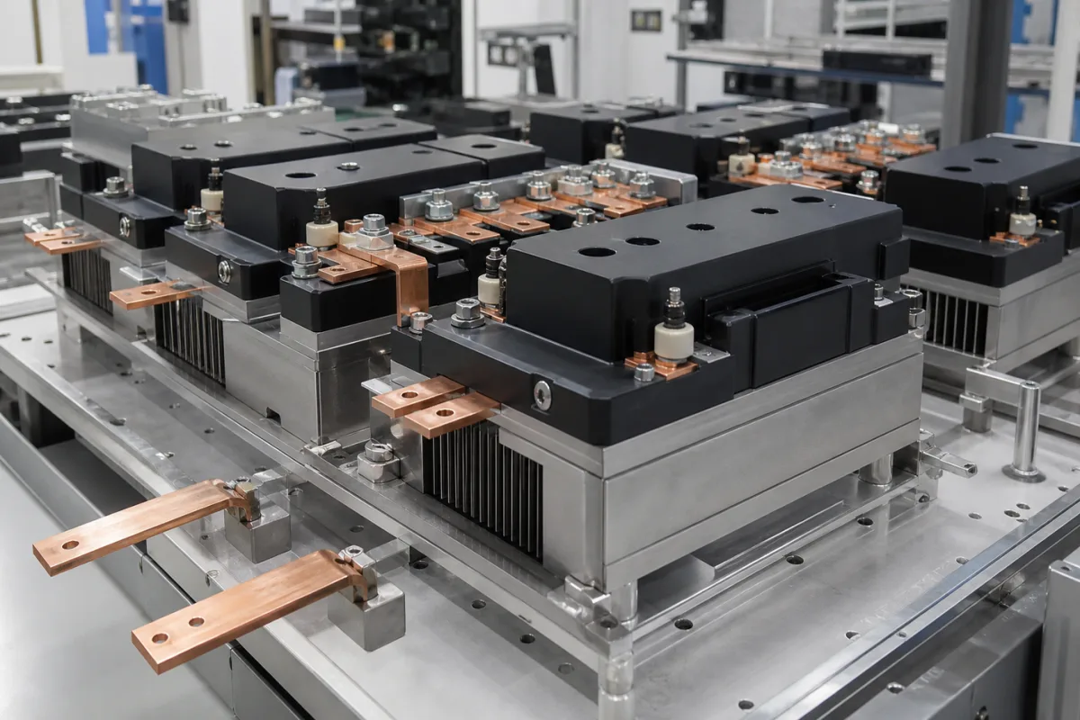
Thyristor switching modules for capacitor banks: the electronic switch that connects power-factor capacitor steps in milliseconds instead of a contactor
Dynamic power factor correction · thyristor switches that put capacitor steps on and off the grid in about 5 ms, 10–24 V DC triggering, capacitors left charged at peak voltage, superfast fuses, current-limiting reactors and heat sink limits
Where the reactive load changes within seconds, as on welders, presses, cranes and lifts, power-factor capacitor steps are switched by thyristor modules rather than contactors, so that each step can be switched in and out repeatedly to follow the load. That speed comes with conditions on the capacitors, fuses, reactors and cooling around the module.
Thyristor (static) switching modules for low-voltage power factor correction capacitor steps, from about 12.5 to 120 kvar per module at 380–690 V: switching time, triggering, two- and three-phase switching, the voltage left on switched-off capacitors, discharge resistors, current-limiting and detuning reactors, semiconductor fuses and heat sink cooling. Thyristor power controllers for resistive heating loads are covered on the SCR power controllers for electric heating page; solid-state relays on the Solid state relay (SSR) page; the controller that decides which steps to switch on the Intelligent controller (power factor controller) page; contactors for capacitor steps on the Contactors for capacitor bank switching page; and complete banks on the Capacitor bank for power factor correction and Power capacitor bank cabinet pages.
CNFX editorial research · Sources checked October 13, 2026 · 4 sources
Switching a capacitor step in about 5 ms: what three makers' modules are rated for
Circutor describes its EM-series static switching units as building blocks for capacitor banks in installations with quick and large load fluctuations, in intervals from fractions of a second to 8 or 10 seconds, connecting and disconnecting capacitors in milliseconds; it names welding units, cranes and lifts. [3] TDK lists presses, welding machines, elevators, cranes and wind turbines for its TSM-LC modules, which it says switch PFC capacitors within a few milliseconds without abrasion. [1]
TDK states that the N1 module adapts its switching by microprocessor to capacitor branches with or without a detuning reactor, monitors voltage, phase and temperature with two status LEDs, and can be cascaded where a larger step is needed. [1] The N690 switches two phases, which is why it needs no neutral. [2] Lovato's module also switches two phases and lists compliance with IEC/EN 60947-4-3. [4]
Editorial calculation: a 120 kvar step at 480 V draws 120,000 / (√3 × 480) ≈ 144 A, which is the Lovato module's rated current; a 50 kvar step at 400 V draws 50,000 / (√3 × 400) ≈ 72 A, inside the 75 A TDK gives for the N1. [4][1]
12–24 V DC (8–30 V), voltage-free input or RS485; two controlled phases; peak inverse voltage 2,200 V [4]
Two built-in fans, NTC probe input; 212 × 301 × 216 mm, 6.68 kg [4]
State the grid voltage, step size in kvar, whether the steps are detuned and at what tuning, how the controller will trigger the module (DC signal, contact or bus), and how fast the load changes.
02
Capacitors left charged at peak voltage: the capacitor, discharge-resistor and reactor rules that follow
TDK warns that, because of how the thyristor module switches, the capacitors stay charged to the peak value of the grid voltage even when the step is switched off. It therefore requires 440 V capacitors in a non-detuned bank on a 400 V grid and 480 V capacitors in a detuned one. [1]
The same caution calls for special high-voltage discharge resistors in place of standard ones, because they see twice the peak grid voltage; forbids fast discharge reactors, which are a DC short circuit; and makes two current-limiting reactors per module mandatory in banks without detuning reactors. Electronic switches give no electrical isolation when off, so parts of the bank may be touched only after the capacitor discharge time has elapsed, even with the main breaker open, and warning signs for residual voltage are required. [1][2]
Editorial calculation: on a 400 V grid the peak line voltage is √2 × 400 ≈ 566 V, so a discharge resistor across a switched-off step can see about 2 × 566 ≈ 1,130 V. [2]
Circutor specifies RC protection against 1,000 V/µs for du/dt and limits di/dt to 100 A/µs with a 12 µH inductor, not supplied, in series with the capacitor. [3] TDK gives the re-switching time as dependent on the degree of detuning and the discharge resistor. [1]
Confirm the capacitor voltage rating against the module maker's rule, the discharge resistor type, and whether series current-limiting reactors or detuning reactors are fitted in each step.
03
Superfast fuses, power loss and heat sink temperature
TDK makes superfast electronic fuses mandatory ahead of each module to protect the semiconductors, giving 3 × 125 A for a 50 kvar step and 3 × 63 A for a 25 kvar step on the N1 (NH, AC 690 V). [1]
TDK gives the N1's power loss as Pv (W) = 2.0 × I (A), and 150 W (typ.) at 400 V and 50 kvar; the N690's as Pv = 2.4 × I, approx. 150 W at nominal current. Both are passively cooled, must hang vertically with at least 150 mm clear above and below, should not be stacked one above another, run at −10 to +55 °C ambient at nominal load, and will not switch back on after an over-temperature fault until the heat sink is below 50 °C. [1][2]
Circutor limits the heat sink of its EMF unit to 80 °C at a maximum ambient of 40 °C, with a 90 °C thermostat. [3] Lovato's fan-cooled module runs from −20 °C to +45 °C without derating and up to 55 °C with derating, below 2,000 m. [4]
Editorial calculation: with TDK's N1 formula, a 50 kvar step at 400 V (about 72 A) dissipates roughly 2.0 × 72 ≈ 144 W, so a bank with eight such steps switched on puts about 1.2 kW into the cabinet from the modules alone. The eight-step bank is an assumed example. [1]
04
Data for a thyristor switching module
Paste it into your enquiry below or into an email to a maker, then replace every bracket.
Grid: [voltage; frequency; neutral available]
Steps: [kvar per step; number of steps; detuning factor]
Load: [process; how fast reactive power changes]
Control: [trigger signal; controller make; bus option]
Capacitors: [voltage rating; discharge resistors]
Protection: [superfast fuse rating; current-limiting reactors]
Cabinet: [ambient temperature; cooling; mounting space]
Explore company information and manufacturing capabilities, then discuss the scope of your project with a relevant supplier.
Share this page
Compiled and source-reviewed by the CNFX editorial team.
Each manufacturer above links to the page on that company's own website where the product is listed, with the date we checked it. How we source and review
· Page last updated 13 October 2026
Buyer questions
How fast does a thyristor module switch a capacitor step?
TDK gives approx. 5 ms for its TSM-LC-N1 and N690 modules; Circutor says its EM units connect and disconnect capacitors in milliseconds. [1][2][3]
Why do thyristor-switched banks need higher-voltage capacitors?
TDK states that the capacitors stay charged to the grid peak voltage even when switched off, and requires 440 V capacitors without detuning and 480 V with detuning on a 400 V grid. [1]
What fuses protect a thyristor switching module?
Superfast electronic fuses ahead of the module; TDK lists 3 × 125 A for 50 kvar and 3 × 63 A for 25 kvar. [1]
Why do some modules switch only two phases?
TDK's N690 and Lovato's DCTL control two phases; TDK notes the N690 then needs no neutral conductor. [2][4]
Sources and what still needs a direct check
Sources checked 2026-10-13. TDK Electronics datasheets for the TSM-LC-N1 and TSM-LC-N690 thyristor modules, Circutor's EMF-40/400 static switching unit page, and Lovato Electric's DCTLA4801200 datasheet.