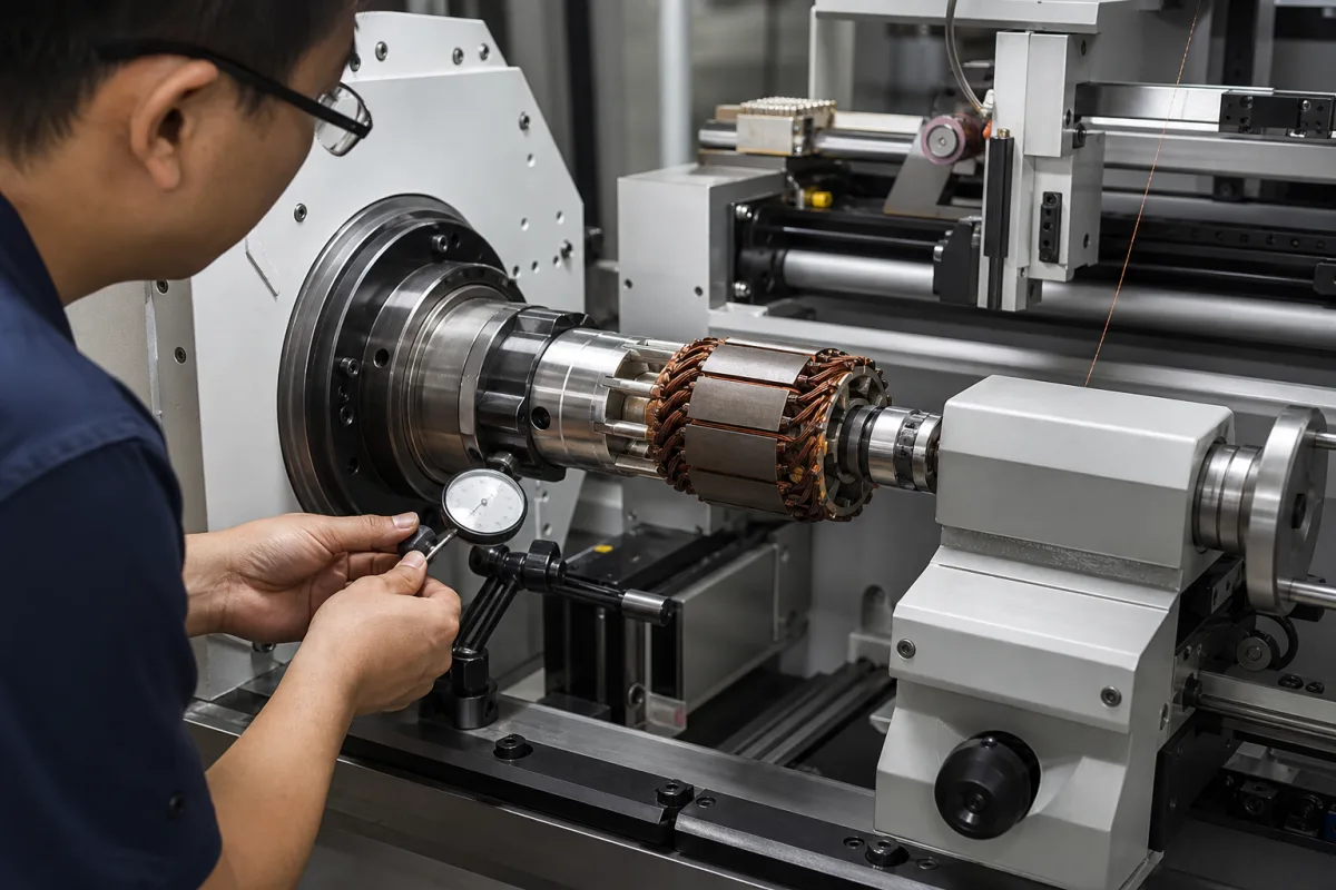
Winding spindle assembly: the bearing-mounted headstock spindle that turns the coil former, and how its runout and speed hold up in service
The rotating headstock unit of a coil winder · bearing layout with a floating rear pair, circular runout from 0.001 mm new to 0.011–0.018 mm after a year, 15,000–18,000 rpm small-coil spindles against 10–1,000 rpm motor-coil spindles
Every turn of wire in a coil is laid on a former, bobbin or core that the winding spindle holds and rotates. The rest of the winder (traverse, tensioner, counter) works relative to that spindle, so its bearing arrangement, its runout and the speed and torque it can sustain set limits for the whole machine. This page looks at the spindle unit itself: how its bearings are arranged and why, what runout figures have been published for it new and after a year of three-shift use, and how far apart small high-speed spindles and slow, high-torque motor-coil spindles sit.
Spindle assemblies of coil winding machines: the spindle box or headstock, spindle shaft, front and rear bearings, spacer sleeve, bearing cap and timing-belt wheel, and the formers or tooling the spindle carries. Complete machines for transformer, reactor and inductor coils (linear, foil, heavy-coil and toroidal winders) are covered on the Transformer winding machine page, and turn and length counting on the Counter system for cable and wire length page. Machine-tool spindles are covered on the Spindle assembly (direct-drive spindle unit) and Main spindle unit with external belt or gear drive pages, and super-precision bearings on the Precision bearings page. Wire tensioners, traverse guides and magnet wire are outside this page.
CNFX editorial research · Sources checked October 12, 2026 · 3 sources
Two fixed front bearings and two floating rear bearings: why Hongfa moved away from the three-bearing spindle
Xiamen Hongfa Industrial Robot's US patent 10,934,127 (Chinese priority 14 September 2017) starts from a winder spindle built on three bearings and driven, like its neighbours, by a timing-belt wheel at the rear. [1]
The patent's reasoning is thermal: at high speed the bearings heat the spindle and box, and a rear outer ring that can slide axially takes up that expansion instead of loading the bearings, while equal numbers of bearings at each end spread the force more evenly along the shaft. [1]
Between the pairs, a sleeve sits on the shaft clear of the bore wall and presses on the inner rings of front and rear bearings; shoulders on the shaft and an extension of the timing-belt wheel clamp the inner rings from outside. The bore of the spindle box is narrower in the middle than at its ends, forming the limit steps that stop the box from drifting far enough to let the bearings at the other end leave the bore. [1]
Editorial calculation: raising the spindle from 15,000 to 18,000 rpm is a 20% increase in speed, and so in turns laid per minute when the coil and traverse can follow.
Angular contact bearing must be replaced by a professional [1]
Free outer ring absorbs machining error and makes assembly, disassembly and replacement simpler [1]
Ask which end of the spindle is axially located, how the other end accommodates thermal growth, the bearing type and count at each end, and whether bearings can be replaced on site.
02
Circular runout from 0.001 mm at assembly to 0.011–0.018 mm after a year, against the bearing grade
Hongfa defines circular runout as the change in outer diameter measured on a cross-section of the spindle over one turn, and publishes how it grew in the two designs. [1]
The patent text prints the 1,500 rpm and one-month figures for the older spindle as "0.005 vmm" and "0.01 min"; the table above reads both as millimetres, consistent with the rest of the series. [1]
For scale, MinebeaMitsumi's excerpt of JIS B 1514-1 gives the maximum radial runout of the inner ring (Kia) for bearings up to 18 mm bore as 10 µm in grade 0, 4 µm in grade 5, 2.5 µm in grade 4 and 1.5 µm in grade 2; the company states that its products are based on JIS B 1514 and ABMA 12.2 and 20. [2]
Editorial calculation: after a year the Hongfa spindle's 0.011 mm (11 µm) exceeds even the 10 µm grade 0 inner-ring limit, and the older spindle's 0.018 mm is 1.6 times that of the new design. The patent figures are for an assembled spindle and its bore diameter is not stated, so they cannot be read as bearing Kia values; they show how far runout drifts from the 0.001 mm at assembly.
Ask for runout measured on the spindle nose at delivery and the method used, the bearing tolerance grade, the bore diameter, and what runout the supplier treats as the replacement point.
03
Ten to 1,000 rpm with up to 4,500 N·m: spindles that carry formers for motor coils
At the other end of the range from small high-speed spindles, Schleich builds PC-controlled winding machines for producing and repairing electric motors from frame size 56 to 450, as single-spindle, dual-spindle and flyer winders. [3]
On these machines the formers are installed first, and the distance between them is then adjusted automatically by an electric motor drive before winding starts; the motor database stores coil dimensions, number of turns, wire diameter and rpm for each motor. [3]
Editorial calculation: the top of Schleich's range, 1,000 rpm, is one-eighteenth of the 18,000 rpm in Hongfa's patent, while Schleich lists torque up to 4,500 N·m for spindles that carry formers up to 2,000 mm across. The two sources sit at opposite ends of the spindle range, so the speed and torque to specify come from the coil and former being wound, not from either catalogue maximum.
230 V or 400 V, 50 Hz, or to customer specification [3]
Give the largest former or coil diameter and mass, the wire bundle (strands × diameter), the speed and torque needed, and whether one or two spindles are wanted.
04
What to send for a winding spindle assembly
Paste it into your enquiry below or into an email to a maker, then replace every bracket.
Machine: [winder make and model; number of spindles; spindle pitch]
Coil: [former or bobbin type; diameter; mass]
Speed and torque: [maximum rpm; torque at that speed]
Bearings: [type and count each end; tolerance grade; located and floating ends]
Runout: [at delivery; measurement point and method; replacement limit]
Drive: [timing-belt wheel or direct motor; shaft end and key]
Duty: [hours per day]
Explore company information and manufacturing capabilities, then discuss the scope of your project with a relevant supplier.
Share this page
Compiled and source-reviewed by the CNFX editorial team.
Each manufacturer above links to the page on that company's own website where the product is listed, with the date we checked it. How we source and review
· Page last updated 13 October 2026
Buyer questions
How fast can a coil winding spindle run?
Xiamen Hongfa's patent describes a three-bearing spindle limited to 15,000 rpm and a two-plus-two bearing design raised to 18,000 rpm. Schleich's WM 2000 motor-coil winder runs 10–1,000 rpm with up to 4,500 N·m. [1][3]
Why is one end of the spindle left free to move axially?
In Hongfa's design the rear bearing outer rings can slide axially, taking up thermal expansion at high speed and machining error, which the patent links to higher speed, less damage and easier bearing replacement. [1]
How much does winding spindle runout grow in use?
Hongfa reports 0.001 mm at installation rising to 0.011 mm after a year for its design and 0.018 mm for the older three-bearing spindle. [1]
What radial runout do precision bearing grades allow?
MinebeaMitsumi's JIS B 1514-1 excerpt gives inner-ring Kia up to 18 mm bore as 10 µm (grade 0), 4 µm (grade 5), 2.5 µm (grade 4) and 1.5 µm (grade 2). [2]
Sources and what still needs a direct check
Sources checked 2026-10-12. Bearing layouts, speeds, service life and runout series come from Xiamen Hongfa Industrial Robot's US patent 10,934,127; bearing-grade runout limits from MinebeaMitsumi's engineering page on JIS B 1514-1; motor-coil spindle speed, torque and formers from Schleich's winding machine brochure.