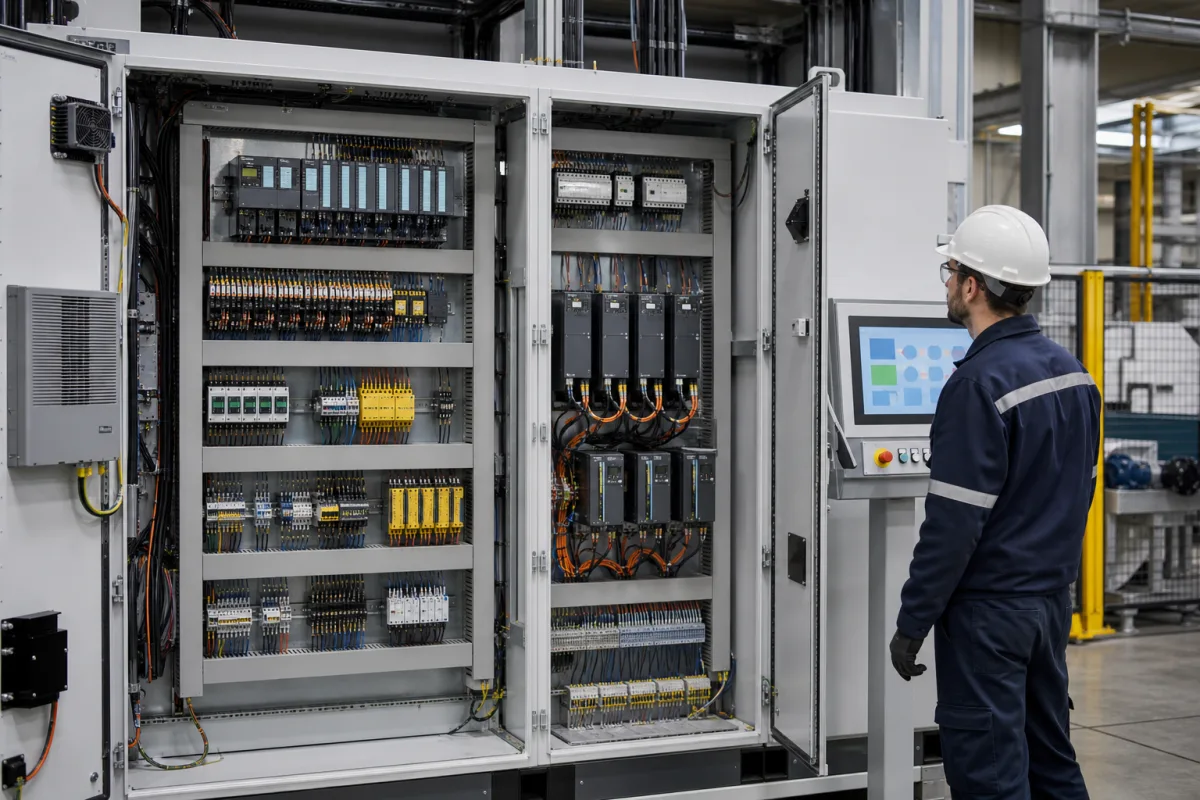
Control system cabinet: the machine control panel that houses PLC, drives and protection
Machine control cabinets · Drives, breakers, contactors and PLC in one enclosure, heat dissipation and fan sizing, interrupting ratings and working space in front of the cabinet
This page covers the control cabinet of a machine or process line: the enclosure, mounting plate and wiring that hold the PLC and I/O, variable-frequency drives, circuit breakers, contactors, power supplies, terminals and cooling, with an HMI on or near the door. Ask three things first: how the cabinet dissipates its heat loss at your ambient temperature, what short-circuit and interrupting ratings its protective devices carry at the installation, and how much working space the location gives in front of it.
Machine and process control cabinets (industrial control panels) with PLC, drives, protection and control components, built for OEM machines and production lines. PLC-based motion control and controller selection are covered on the Industrial control systems page. Power distribution switchboards, motor control centres and the machines that contain such cabinets are outside this page.
CNFX editorial research · Sources checked October 12, 2026 · 4 sources
Rittal's climate control catalogue gives the basis: in natural convection the heat loss is dissipated through the enclosure panels as long as the ambient temperature is lower than the internal temperature, and the heat emitted by the enclosure surface is QS = A·k·ΔT, where A is the effective heat-dissipating surface to IEC 890, ΔT the temperature difference and k the heat transfer coefficient, 5.5 W/m²K for sheet steel; the maximum internal rise is the installed heat loss divided by A·k. [1]
For fan-and-filter units Rittal gives the required air flow as V = f·QV ÷ ΔT, with the factor f = 3.1 m³·K/(W·h) at 0–100 m above sea level, 3.2 at 100–250 m, 3.3 at 250–500 m, 3.4 at 500–750 m and 3.5 at 750–1,000 m, and states that the right unit dissipates the specified heat loss while keeping to the maximum internal temperature. [2]
Editorial calculation: with an assumed 4 m² effective sheet-steel surface and 400 W of drive and power-supply loss, the rise is 400 ÷ (4 × 5.5) ≈ 18 K, so a 35 °C hall would give about 53 °C inside; holding a 10 K rise at sea level with a fan instead needs about 3.1 × 400 ÷ 10 = 124 m³/h. [1][2]
Give the supplier the component list with heat losses, the cabinet size and installation (free-standing, against a wall, in a row), ambient temperature range and altitude, dust or wash-down conditions, and the maximum internal temperature the components allow.
02
Plan protective-device ratings and working space
OSHA's 29 CFR 1910.303 requires that equipment intended to interrupt current at fault levels have an interrupting rating sufficient for the nominal circuit voltage and the current available at its line terminals, and that the overcurrent devices, total impedance and component short-circuit current ratings be selected and coordinated so a fault is cleared without extensive damage to the circuit's components. [3]
For equipment at 600 V or less that may be examined, adjusted, serviced or maintained while energised, the same section sets the depth of working space by Table S-1: 0.9 m (3.0 ft) for 0–150 V to ground in all three conditions, and for 151–600 V 0.9 m (3.0 ft) with exposed live parts on one side only (Condition A), 1.0 m (3.5 ft) with grounded parts opposite (B) and 1.2 m (4.0 ft) with live parts on both sides (C). The width must be the equipment width or 762 mm (30 in), whichever is greater, doors must open at least 90°, and headroom must be at least 1.98 m (6.5 ft) for installations built on or after 13 August 2007. [3]
Editorial note: OSHA applies these rules to the installation in the United States; ask the cabinet builder which standards the panel itself is built and marked to for your market, and for the short-circuit rating it can state at your available fault current.
03
Sealed, fan-and-filter and OEM control cabinet arrangements
The arrangement sets heat dissipation and access.
Arrangement
What the source states
Ask for
Sealed cabinet, natural convection
Heat leaves through the panels; QS = A·k·ΔT, k = 5.5 W/m²K for sheet steel. [1]
12 companies list this product among what they make. Company figures are quoted from each
company's own website; every card states where the relationship came from.
CHINT Group
Manufacturing site to be confirmed for the order
Lists a food and beverage control system solution for packaging equipment using NVF5 drives, NXM circuit breakers, NXC contactors and an NTP1 touch panel.
Explore company information and manufacturing capabilities, then discuss the scope of your project with a relevant supplier.
Share this page
Compiled and source-reviewed by the CNFX editorial team.
Each manufacturer above links to the page on that company's own website where the product is listed, with the date we checked it. How we source and review
· Page last updated 13 October 2026
Buyer questions
How do I check if a control cabinet will overheat?
Rittal's basis is QS = A·k·ΔT with k = 5.5 W/m²K for sheet steel; the internal rise is the heat loss divided by A·k. [1]
How much air does a cabinet fan need to move?
Rittal gives V = f·QV ÷ ΔT, with f = 3.1 m³·K/(W·h) at sea level rising to 3.5 at 750–1,000 m. [2]
How much space is needed in front of a control cabinet?
OSHA 29 CFR 1910.303 Table S-1 sets 0.9–1.2 m depth depending on voltage and conditions, a width of at least 762 mm and 1.98 m headroom for newer installations. [3]
Sources and what still needs a direct check
Sources checked 2026-10-12. Rittal describes its own calculation basis; OSHA's regulation applies to installations in the United States; Chint describes its own OEM solution.