Editorial Technical Reference

Precision Tooling (Die & Punch)

This page explains how Precision Tooling (Die & Punch) is classified within Fabricated Metal Product Manufacturing. Technical values and manufacturer relationships are research references; confirm the current specification and supplier evidence for each order.

Technical Definition & Core Assembly

Specialized tooling components used for cutting, forming, or shaping materials in precision pressing operations
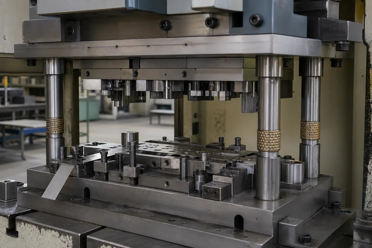
Representative product image. Confirm appearance and specifications with the manufacturer.

Product Specifications

Technical details and manufacturing context for Precision Tooling (Die & Punch)

Definition
Precision tooling consisting of matched die and punch sets that work together within a Precision Pressing Station to perform accurate cutting, punching, or forming operations on various materials. The die provides the stationary cutting or forming surface, while the punch is the moving component that applies force to the workpiece against the die. This product is a component used in the fabrication of metal products, specifically in stamping and forming processes. The tooling is manufactured from materials such as tool steel, carbide, and high-speed steel, which are selected for their hardness, wear resistance, and toughness. Key parameters include die height (50–300 mm), punch diameter (1–50 mm), working pressure (1.0–1.6 MPa), tolerance grade (IT5–IT7 per ISO 286), surface roughness (0.2–0.8 µm Ra per ISO 1302), hardness (58–62 HRC per ISO 18265), operating temperature (-20 to 120°C), maximum strokes per minute (60–120 min⁻¹), die material (Cr12MoV per GB/T 1299), punch material (W6Mo5Cr4V2 per GB/T 9943), and weight (5–50 kg). These values are reference ranges and must be verified for the specific model and application. The tooling is designed to fit specific press shut heights and must be selected based on the required operation, material type, and production volume. Proper alignment and maintenance are critical for consistent performance and longevity. Users should consult the legal manufacturer or supplier to confirm exact specifications and compliance with applicable standards.
Working Principle
The punch moves downward with controlled force and precision alignment to press material against the die, which contains the desired shape or cutting edge. This action either cuts through material (blanking/punching) or forms it into specific shapes (forming/bending) through plastic deformation or shearing. The die is stationary and provides the counter-surface, while the punch is the moving component. The process requires precise alignment and force control to achieve accurate dimensions and surface finish. The tooling must be properly installed and maintained to ensure consistent operation and to prevent premature wear or failure.
Common Materials
Tool steel, Carbide, High-speed steel
Technical Parameters
ParameterTypical rangeNotes & selection driver
Die Height50–300 mmDetermines press shut height compatibility
Punch Diameter1–50 mmStandard range; custom sizes available
Working Pressure1.0–1.6 MPa
Tolerance GradeIT5–IT7Higher precision for critical dimensionsISO 286
Surface Roughness0.2–0.8 µm RaSmoother finish reduces wearISO 1302
Hardness58–62 HRCHigher hardness increases wear resistanceISO 18265
Operating Temperature-20–120 °CAbove 120°C may soften tool steel
Max Strokes per Minute60–120 min⁻¹Depends on press and die design
Die MaterialCr12MoVHigh carbon chromium steelGB/T 1299
Punch MaterialW6Mo5Cr4V2High speed steel for wear resistanceGB/T 9943
Weight5–50 kgVaries with size and complexity

Ranges are indicative industry figures for RFQ preparation, not a supplier commitment. Confirm every value and standard with the legal manufacturer before ordering.

Components / BOM
  • Punch Part
    Moving component that applies force to cut or form material
    Material: Tool steel or carbide
  • Die Part
    Stationary component that provides cutting edge or forming surface
    Material: Tool steel or carbide
  • Guide Posts/Bushings Part
    Ensures precise alignment between punch and die
    Material: Hardened steel
  • Stripper Plate Part
    Removes material from punch after cutting operation
    Material: Steel

Applied To / Applications

This component is essential for the following industrial systems and equipment:

Industrial Ecosystem & Supply Chain Structure

Complementary Systems
Downstream Applications
Specialized Tooling

Application Fit & Sizing Matrix

Operational Limits
pressure: Up to 1500 MPa
other spec: Surface finish: Ra 0.2-0.8 μm, Hardness: 58-62 HRC
temperature: -50°C to 300°C
Media Compatibility
✓ Sheet metal (steel, aluminum) ✓ Plastic films (PET, PVC) ✓ Composite materials (carbon fiber, fiberglass)
Unsuitable: Abrasive slurries or highly corrosive chemical environments
Sizing Data Required
  • Material thickness and hardness
  • Required cutting/forming force
  • Production volume and tool life expectancy

Reliability & Engineering Risk Analysis

Failure Mode & Root Cause
Edge chipping or cracking
Cause: Excessive localized stress from misalignment, improper material selection, or overloading during stamping operations
Wear and dimensional degradation
Cause: Abrasive action from workpiece materials, lack of proper lubrication, or gradual material fatigue from cyclic loading
Maintenance Indicators
  • Visible burrs or rough edges on stamped parts indicating tool wear
  • Unusual knocking or scraping sounds during operation suggesting misalignment or excessive clearance
Engineering Tips
  • Implement regular precision alignment checks and proper lubrication schedules using manufacturer-recommended lubricants
  • Establish a preventive maintenance program with scheduled inspections, edge condition monitoring, and controlled storage to prevent corrosion and physical damage

Indicative industry ranges for design and RFQ preparation. Confirm the exact figures and applicable standard with the manufacturer before specifying.

Compliance & Manufacturing Standards

Applicable Standards
ISO 2768-1: General tolerances for linear and angular dimensions ANSI B94.2: Cutting Tools - Punches and Dies DIN 8580: Manufacturing processes - Terms and definitions, division

Quoted from the published standard.

Manufacturing Precision
  • Bore diameter: +/-0.005mm
  • Flatness: 0.01mm per 100mm
Quality Inspection
  • Dimensional verification with CMM (Coordinate Measuring Machine)
  • Hardness testing (Rockwell C scale)

Manufacturers of Precision Tooling (Die & Punch)

Manufacturer profiles associated with Precision Tooling (Die & Punch).

Sourcing Precision Tooling (Die & Punch) from China?
Tell us your specification and target quantity — we will match it against manufacturer records and come back with the factories that fit.
Request manufacturers We manufacture this

Manufacturer listings support early research and capability understanding. They are not certification, ranking, or transaction guarantees.

Technical documentation
Request current drawings, revision history, and a signed specification sheet.
Manufacturing capability
Verify equipment lists, process limits, capacity, and representative production evidence.
Inspection readiness
Confirm test methods, calibrated equipment, sampling plans, and traceable reports.
Supplier transparency
Check the legal entity, factory address, ownership, certifications, and direct contacts.

CNFX does not score or rank suppliers. Buyers must verify all claims and documents with the legal manufacturer before ordering.

Supply Chain Compatible Machinery & Devices

Industrial Tube Bending Machine

An industrial tube bending machine is a CNC-controlled device designed to precisely bend metal tubes and pipes to specific angles and radii.

Explore Specs →
Precision Linear Motion Guide Rail

Precision linear guide component for smooth, accurate motion in industrial machinery

Explore Specs →
Precision Aluminum Extrusion Profile

Precision aluminum extrusion profiles are semi-finished structural components produced by forcing heated aluminum alloy through a shaped die.

Explore Specs →
Precision Hydraulic Valve Spool

A precision hydraulic valve spool is a cylindrical metal component that slides within a valve body to regulate hydraulic fluid flow, pressure, and direction.

Explore Specs →

Frequently Asked Questions

What materials are used for the die and punch?

The die is typically made of high carbon chromium steel (Cr12MoV) per GB/T 1299, and the punch is made of high-speed steel (W6Mo5Cr4V2) per GB/T 9943. Other materials like carbide may be used for specific applications, but these are the reference grades listed.

What is the typical tolerance grade achievable?

The tolerance grade is IT5 to IT7 as per ISO 286. This indicates a high precision level suitable for critical dimensions, but the actual achievable tolerance depends on the specific tooling design and press conditions.

How do I determine the correct die height for my press?

Die height ranges from 50 to 300 mm. It must match the press shut height to ensure proper operation. Always verify the required die height with the press specifications and the tooling manufacturer.

What maintenance is required for these tooling components?

Regular inspection for wear, proper lubrication, and alignment checks are essential. Surface roughness and hardness should be monitored. If operating temperature exceeds 120°C, tool steel may soften, so cooling may be needed. Follow manufacturer guidelines for maintenance intervals.

Data Basis

Editorial classification, named public sources where available, and source-reviewed manufacturer records.

Preliminary Technical Classification
This page supports structured research, RFQ preparation, and supplier evaluation. It does not replace buyer-led supplier qualification, standards review, or technical approval.
Buyer enquiry

Request manufacturing insight for Precision Tooling (Die & Punch)

Ask for use case, specification boundaries, supplier type, and RFQ preparation information for this product.

Where it goes
Straight to the CNFX editorial desk, and to the manufacturer if this product is linked to a claimed profile. Nothing is broadcast to a supplier list.
Your details stay here
We do not sell or rent enquiry data, and we do not add you to a mailing list. Used only to answer this request.
No commission, no middleman
CNFX is a directory. We take no cut of any order and never negotiate on a supplier's behalf.
What we don't claim
A listing is not an endorsement. Qualify every supplier and verify every figure yourself before ordering.

Your business information is used only to process this request.

Thank you! Your message has been sent. We'll respond within 1–3 business days.
Sorry, we couldn't send your message. Please try again, or email us at contact@cnfx.com.

Need to Manufacture Precision Tooling (Die & Punch)?

Compare manufacturer profiles with relevant product and process capability.

Previous Product
Welding Positioner
Last Product
Get QuotesChat