Metal forming · Rotary draw tooling, D of bend and wall factor
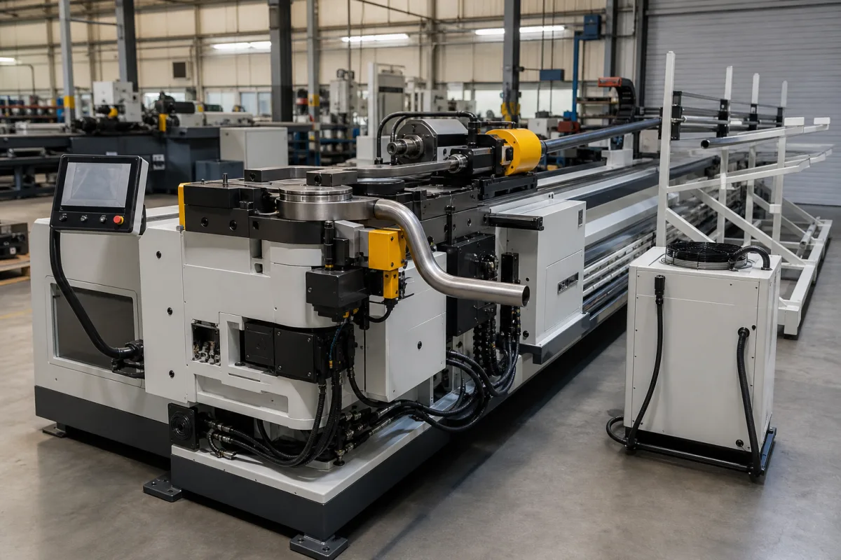
A rotary-draw bender wraps the tube around a bend die while a clamp die holds it and a pressure die reacts the load. Thin walls and tight radii need a mandrel and wiper die to stop collapse and wrinkles. Start from your tube and bend radius, and the tooling and machine follow.
NC and CNC rotary-draw tube and pipe bending machines with servo or hydraulic bending, feed and rotation axes. Hand benders, induction pipe bending and roll benders are outside this page.
CNFX editorial research · Sources checked October 12, 2026 · 4 sources
In The Fabricator, Paul McGowan defines the D of bend as the centreline radius (CLR) divided by tube OD, and the wall factor as OD divided by wall thickness. In rotary-draw bending the outside wall thins and collapses while the inside compresses and wrinkles; tighter D of bend and higher wall factor make both worse. [1]
His example: a 2 in OD tube with 0.065 in wall at 4 in CLR bent cleanly, but the same OD with 0.035 in wall at 3 in CLR wrinkled inside the bend. Editorial calculation: the first is a 2D bend with wall factor about 31, the second a 1.5D bend with wall factor about 57. [1]
Send the supplier drawings of the bent parts: tube material, OD, wall, every CLR, bend angles, distances between bends and tolerances. Tooling and machine size follow from these.
02
Choose the tooling
McGowan lists the minimum rotary-draw tooling as a bend die and a clamp die, with a pressure die maintaining pressure at the tangent to provide the reaction force. Thick walls at large radii may need nothing more; harder jobs add a mandrel inside the tube to control the outside radius shape, and a wiper die to support the inside radius and wipe out wrinkles. He recommends a wiper die for thin-wall mandrel bending. [1]
He suggests square-back wiper dies for thin walls and tight bends (he cites 1.25D or lower), such as a 2D bend at wall factor 150, and wiper holders with inserts for less aggressive work such as 2D at wall factor 25. He gives a wiper tip setting of 0.060–0.300 in behind tangent; wipers in aluminium bronze suit stainless steel, titanium and nickel alloys, and steel or chrome-plated steel suit mild steel, copper and aluminium. [1]
Ask the supplier to quote tooling for each OD and CLR and to confirm which bends need a mandrel and wiper.
03
Size the machine and its axes
Supplier specifications show what to compare. BLMA's DW63CNC-5AMSV, for example, lists a maximum capacity of Φ63 × 3 mm, maximum bending radius R300 mm, 190° maximum bend, 3,600 mm feed length, servo-driven feed and rotation with hydraulic clamping and mandrel, bending speed up to 80°/s, and ±0.1° bend and rotation and ±0.1 mm feed accuracy. [2]
Check what material and wall the capacity rating assumes, what it means for your material and wall factor, and whether the machine can make every radius on your part and handle the distance between your bends.
04
Compare what suppliers offer
Suppliers linked to this page list NC and CNC pipe and tube benders alongside tube end-forming, cutting and sheet-metal machinery. [2][3]
BLMA lists NC and CNC pipe benders, tube end-forming machines and bending tooling; GSIE lists CNC tube and pipe benders with end-forming and automation; Almaco, Harting, Durmapress and MYT list CNC tube or pipe benders among sheet-metal machines. [2][3]
05
Rate each bend with the difficulty ratio before asking for quotes
Tube-bender maker BLM GROUP defines the difficulty ratio (DR) of a bend as the outside diameter squared divided by the product of wall thickness and centreline radius: DR = OD² / (WT × CLR). It states that a bend of DR 8 needs a mandrel and wiper die to be free of scratches, wrinkles and small imperfections, and treats a CLR-to-diameter ratio below 1 as an extreme curvature. [4]
Its examples include an automotive air-conditioning tube of 18 mm diameter and 1 mm wall at 11 mm CLR (DR 29) and a motorcycle exhaust tube of 52 mm diameter and 1.5 mm wall at 42 mm CLR (DR 43). BLM adds that feasibility also depends on bend angle, part geometry, tooling size, bending direction, tube material, lubrication, bending torque and thrust force, and lists mandrel position, clamp-die pressure, tube-advance thrust and pressure-die thrust and movement as parameters its electric benders control in the cycle. [4]
Editorial calculation: The Fabricator examples above give DR = 2² / (0.065 × 4) ≈ 15.4 for the clean bend and 2² / (0.035 × 3) ≈ 38.1 for the wrinkled one [1]; both exceed BLM's DR 8 reference; ask which bends get mandrel and wiper tooling.
06
Trace the bender components
This is a functional reference built from the sources cited; it is not one maker's parts list.
Fill the specification fields with values for your parts
A tube bender quotation needs values for your parts and production. The table explains each field, gives published values where a reviewed source states them, and says what to obtain from the supplier.
Explore company information and manufacturing capabilities, then discuss the scope of your project with a relevant supplier.
Share this page
Compiled and source-reviewed by the CNFX editorial team.
Published product pages show what a company offers, not tested performance. Confirm the legal seller, factory and scope for your order. How we source and review
· Page last updated 13 October 2026
Buyer questions
What is D of bend and wall factor?
D of bend is centreline radius divided by tube OD; wall factor is OD divided by wall thickness. Lower D and higher wall factor make bending harder. [1]
When do I need a mandrel and wiper die?
For thin walls and tight radii; a mandrel supports the outside radius and a wiper die prevents wrinkles inside. The Fabricator article recommends a wiper for thin-wall mandrel bending. [1]
How accurate are CNC tube benders?
Suppliers state values such as ±0.1° bend and ±0.1 mm feed for one 63 mm machine; ask for accuracy on your parts. [2]
How can I judge how hard a tube bend is?
BLM GROUP's difficulty ratio is OD squared divided by wall thickness times CLR; the maker states that a bend of DR 8 needs a mandrel and wiper die. [4]
Sources and what still needs a direct check
Sources checked 2026-10-12. The Fabricator is a metal-forming trade publication; Paul McGowan's article explains rotary-draw tooling, D of bend and wall factor. Supplier pages describe their own offers.