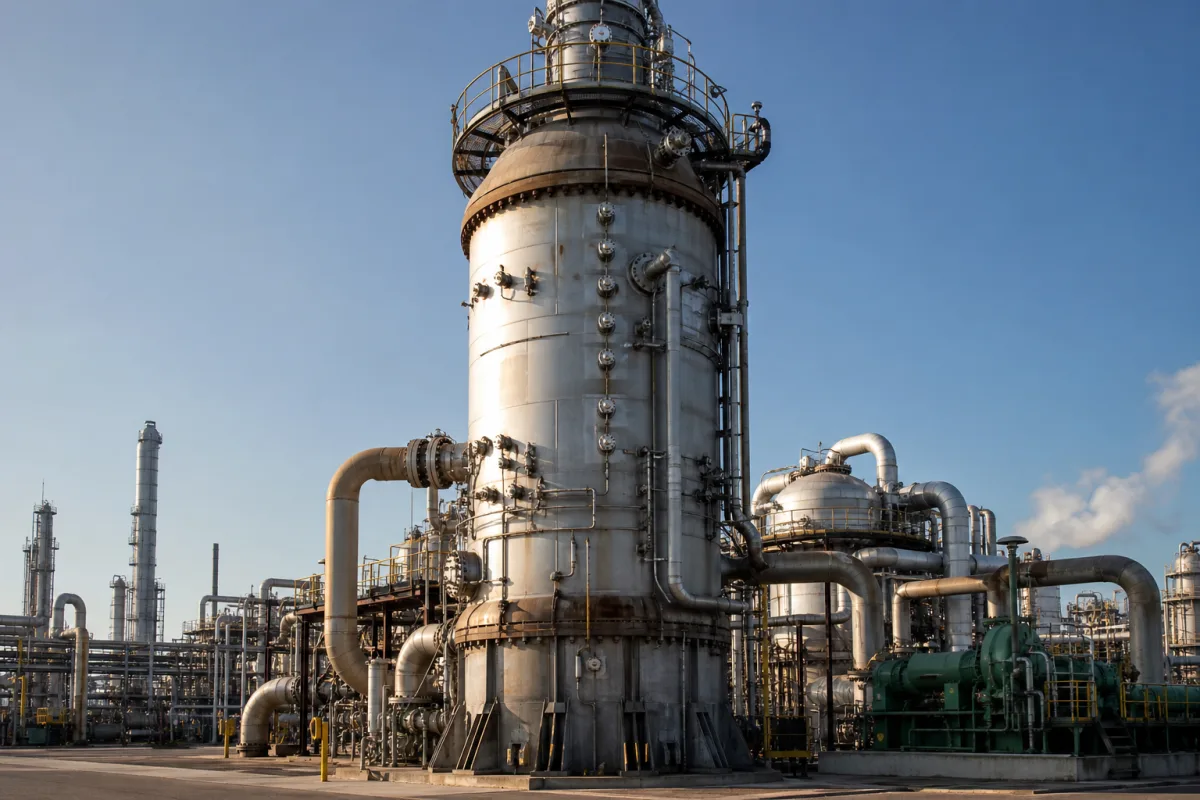
High-pressure ammonia synthesis converters for ammonia plants · Synthesis pressure and temperature, iron catalyst beds and volume, axial or radial gas flow, inter-bed cooling by quench or exchanger, pressure shell and internal cartridge, shell cooling, pressure drop, catalyst loading access
The ammonia synthesis reactor, or converter, is the high-pressure vessel in which hydrogen and nitrogen react over an iron catalyst to form ammonia. It holds a removable internal cartridge of catalyst beds inside a pressure shell and must manage the heat released by the reaction. Ask three things first: what loop pressure, capacity and catalyst volume the plant design sets, whether the beds will run in axial or radial flow and how heat is removed between beds, and how the shell is protected from hot gas and how catalyst is loaded and unloaded.
Ammonia synthesis converters with internal catalyst cartridges for synthesis loops in ammonia plants, including new converters and cartridge retrofits. Synthesis-gas compressors (see high-pressure ammonia synthesis loop centrifugal compressor), reformers, catalyst supplied alone, and laboratory high-pressure autoclaves are outside this page.
CNFX editorial research · Sources checked October 11, 2026 · 4 sources
Set the synthesis pressure, temperature and catalyst
EPA's AP-42 section on synthetic ammonia describes the synthesis step: synthesis gas with a 3:1 hydrogen-to-nitrogen mole ratio from the methanator is compressed to 13,800–34,500 kPa (2,000–5,000 psia), mixed with recycle gas and cooled to 0 °C to condense ammonia; the unconverted gas is recompressed and preheated to 180 °C before entering the synthesis converter, which contains iron oxide catalyst. Ammonia from the exit gas is condensed, and a small purge prevents inert gases such as argon from building up. [1]
The worked example in US patent 4,181,701 runs a radial-flow converter at about 270 kg/cm² g, with a shell stream of 151,480 Nm³/h of synthesis gas entering at about 120 °C. [2]
Editorial calculation: 270 kg/cm² is about 26.5 MPa (× 0.0981), inside the 13.8–34.5 MPa range AP-42 gives for synthesis loops. [2][1]
Give the supplier the plant capacity, loop pressure, inlet gas composition and temperature, catalyst type and volume, number of beds, required conversion and pressure-drop limits, cooling scheme (quench, internal or external exchangers, steam raising), shell design code and materials, maximum shell temperature, catalyst loading and unloading method, and whether a new converter or a cartridge retrofit is required.
02
Choose gas flow, inter-bed cooling and internals
US patent 4,755,362 (Ammonia Casale) describes synthesis reactors as an external pressure shell, described as formed in a single piece, holding an internal cartridge of granular catalyst in one or more beds, with the gas cooled between beds by fresh-gas quench or by exchange with cold inlet gas; it contrasts axial-flow Kellogg-type reactors with four quenched beds and ICI-type reactors with quench lozenges. Its invention inserts two concentric perforated cylindrical walls and a bottom closure in a bed so the gas crosses it substantially radially, reducing pressure drop and energy use. [3]
US patent 4,181,701 (Topsøe) describes a converter with two catalyst beds in radial flow and a heat exchanger mounted centrally in one bed. The feed is split into a shell stream that cools the pressure shell, an exchange stream that cools the central exchanger and a bypass stream for final temperature adjustment; the combined stream passes inward through the first bed, through the exchanger, then radially through the second bed. [2]
Editorial note: radial and axial-radial designs aim at lower pressure drop and smaller catalyst size, while shell-cooling streams keep the pressure shell below the gas temperature; ask the designer for the shell temperature and pressure drop at end-of-run catalyst activity.
03
Check catalyst volume and pressure drop in a worked converter example
Kellogg Brown & Root's European patent application EP 1 419 813 (2004) describes a vertical fixed-bed ammonia converter in which one catalyst zone is split into two mechanically separated volumes, with the feed divided between them and the gas flowing down through each bed. It states that radial and mixed axial-radial flow have become the standard for vertical converters but need a freeboard or other ineffective catalyst volume and care to avoid fluidizing catalyst at the top of a radial bed, which the split design avoids. Its worked examples give the dimensions below. [4]
The patent sizes perforations so that the feed splits essentially 50-50 between the upper and lower beds, loads the lower bed through pipes passing through the upper bed, and states that the arrangement allows the internals to be built as a module lowered into the shell. [4]
Editorial calculation: 567 ft³ is about 16.1 m³ of catalyst and 6.7 psi is about 46 kPa, inside a 12 ft (3.66 m) shell; at the 13,800–34,500 kPa loop pressures in EPA's AP-42, that pressure drop is 0.13–0.33% of operating pressure. Ask each converter supplier for catalyst volume, bed depth and estimated pressure drop on the same basis. [4][1]
Remove reaction heat by quench or exchanger. [3][2]
Scheme; bypass control.
Inlets and bypasses
Distribute shell, exchange and bypass streams. [2]
Nozzles; control.
05
Pressure, bed geometry and shell data the converter designer must return
Shell thickness, material grade, weight, leakage, corrosion allowance and nozzle sizes have no published value in the sources here; they come from the designer's code calculation for your loop pressure.
Field
What it means and published values
Ask the supplier for
Design Pressure
Shell design pressure; loops run 13,800–34,500 kPa. [1]
Design and operating pressure.
Operating Temperature
Bed and outlet temperatures; inlet preheated to 180 °C in AP-42. [1]
Bed temperature profile.
Reactor Volume
Internal volume of the cartridge; one patent example holds 567 ft³ (about 16.1 m³) of catalyst in a 12 ft shell. [4]
Explore company information and manufacturing capabilities, then discuss the scope of your project with a relevant supplier.
Share this page
Compiled and source-reviewed by the CNFX editorial team.
Each manufacturer above links to the page on that company's own website where the product is listed, with the date we checked it. How we source and review
· Page last updated 13 October 2026
Buyer questions
At what pressure does an ammonia synthesis converter operate?
EPA's AP-42 gives synthesis loop pressures of 13,800 to 34,500 kPa (2,000 to 5,000 psia). [1]
Why use radial flow in an ammonia converter?
Patented radial and axial-radial designs pass gas across beds between perforated walls to reduce pressure drop and energy consumption compared with axial flow. [3][2]
How is heat removed between catalyst beds?
By fresh-gas quench or by exchange with cold inlet gas, including an exchanger mounted inside a bed. [3][2]
How much pressure drop does an ammonia converter catalyst zone have?
In KBR's patent EP 1 419 813, a split two-bed zone in a 12 ft shell holding 565–567 ft³ of catalyst has an estimated pressure drop of 6.7–7.6 psi, excluding the heat exchanger. [4]
Sources and what still needs a direct check
Sources checked 2026-10-11. Sources are EPA's emission-factor chapter on synthetic ammonia, which describes the process, and three patents describing converter internals from different applicants; none endorses a supplier.