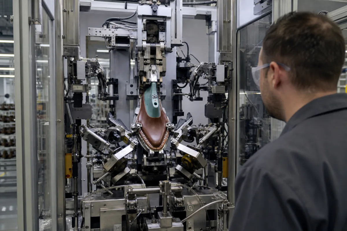
Programmable side and heel-seat lasting station: digitised cement and roller paths, up-drafting at the breast line, and a scanned bite line on the lasted shoe
The programmable station that lasts the sides and heel seat after the toe · cement nozzles and lasting rollers driven along digitised, size-graded paths by stepping motors, rollers about 75 mm behind the nozzles, adhesive cut 20–30 mm before the taught end point, and the bite line marked and scanned on the lasted shoe at about 30 kg/cm mating pressure
A shoe arrives at the side and heel seat laster with its toe already lasted and the rest of the upper still standing up from the insole. The station has to clamp the heel, wipe the heel seat, draw the upper tight at the breast line, and then work forward along both sides, laying adhesive and wiping the margin over the insole, on every size and on left and right shoes. Doing that on programmed paths is what makes it a multi-axis station rather than a set of fixed wipers.
Side and heel-seat lasting stations that work on a shoe after toe lasting, with programmable (stepping-motor or servo) movement of cement nozzles, lasting rollers or wipers along the shoe bottom, heel band and heel seat wipers, and marking and scanning the bite line on the lasted shoe. Pulling-over and toe lasting machines, their pincers and the combined toe, side and heel machine are covered on the Industrial footwear upper stretching machine page; roughing, cement spraying and sole pressing on the lasted upper are covered on the Automated sole-attaching line for cemented shoes page.
CNFX editorial research · Sources checked October 13, 2026 · 3 sources
Cement nozzles and lasting rollers on digitised paths, graded by shoe length
British United Shoe Machinery's application EP 0 511 810 A1 (1992) describes a machine for lasting side and heel seat portions with a shoe support of last pin, toe support and heel band, two side lasting assemblies and a heel seat wiper mechanism. The toe support height is set by a stepping motor and ball screw according to the style of shoe. [1]
Nozzle and roller share a carriage on each side but move independently across and up and down, so each tracks the shoe bottom and ends its path on its own. [1]
Editorial calculation: with the rollers about 75 mm behind the nozzles, the time between adhesive landing and the margin being wiped onto it is 75 mm divided by the carriage speed; at an assumed 50 mm/s that is 1.5 s, and at 25 mm/s it is 3 s. The adhesive's open time has to cover that interval.
Step in the cycle
What the application describes
Start
Side clamp members close on the shoe; the adhesive nozzles move down onto the insole and then heelward, driven by a stepping motor, to the backseam region next to the insole edge, beneath any in-flanged margin [1]
Adhesive along the sides
Adhesive is fed and stepping motors move the nozzles toeward along a path, preferably parallel to the insole edge, up to the toe-lasted portion [1]
Path control
Paths digitised as coordinate values applied directly to the stepping motors, reversible for left and right shoes and graded to the shoe length measured by a linear potentiometer [1]
Wiping
Rotating rollers with a helical rib follow the nozzles once these are about 75 mm forward of the heel breast line, wiping the margin in and pressing it onto the insole [1]
End of path
With programmed control the boundary of the toe-lasted portion is taught; adhesive feed stops 20–30 mm before it and reverses to suck adhesive back from the nozzle and stop drooling [1]
Unloading
The heel band swings the shoe through about 180° onto a platform that loads successive shoes into successive channels of a heat-setting apparatus [1]
Ask how paths are entered (digitised, taught or scanned), how many sizes one programme grades across, and how left and right shoes are handled.
02
Drawing the upper tight at the heel breast line without breast line pincers
An earlier BUSM and Deutsche Vereinigte Schuhmaschinen application, EP 0 247 831 A2 (1987), deals with the region where heel seat and side lasting meet. When the upper has not been cut correctly to the last, the wipers alone may not conform it there, and creases form in the side portions; breast line pincers had been used to grip the margin and draw the upper up first. [2]
The application lists the drawbacks of those pincers: they need space the side and seat laster does not have, their small jaws make feeding the margin in difficult and time-consuming, more so with automatic loading, and with long counters reaching into the waist an up-pull at the breast line can misplace the counter. Its machine instead traps the margin, with a slipping grip, between a retractable abutment and a counter-abutment on the side lasting assembly, either a face of the fastener-inserting tool at the breast line or an end face of a pre-folding finger in the waist region, as the assembly moves into place, so the upper is drawn over the insole edge without adding time to the cycle. The side lasting assemblies then work progressively along the sides from the breast line, and the application states that the more reliable grip suits automatic loading of shoes. [2]
For styles with long counters, ask where the machine applies its up-draft and whether that point can be moved toward the waist.
03
Marking and scanning the bite line while the shoe is still on its last
Nike's European patent EP 3 572 891 B1 starts from the lasted upper: it is pressed against the sole unit, or a representation of it, and the junction, the bite line, is recorded so that later treatment stays inside the area the sole will cover. [3]
A virtual bite line can also be made without marking the shoe, by tracing the junction with a stylus linked to a 3D representation system or from the break in a projected light line where upper and sole representation meet; the scanning system can rotate around the lasted upper, or the upper can be rotated past it. [3] How the adhesive is then sprayed and the sole pressed on is covered on the Automated sole-attaching line for cemented shoes page.
Editorial note: BUSM's 1992 machine replays a digitised path graded to shoe length; the Nike method measures each lasted upper. Ask which a supplier uses, because a replayed path cannot see a shoe that is out of position on its last. [1][3]
Element
Example given in the patent
Pressure mating the lasted upper and sole representation while the bite line is marked
Ink, pencil, scribed indentation, or fluorescent or infrared ink invisible under normal light [3]
Reading a conditionally visible line
Black light or IR illumination, with images from a first and second camera combined [3]
Laser line generator for the 3D surface scan
40° fan angle, 180 mm line length, 0.108 mm line width, 245 mm working distance, 205–510 mm focusing range [3]
04
What to send a side and heel-seat lasting station supplier
Paste it into your enquiry below or into an email to a maker, then replace every bracket.
Shoes: [styles; size range; left and right; counter length]
Upper and insole: [materials; in-flanged margin or not]
Lasting: [adhesive type and open time; tacks at the heel seat or not]
Paths: [digitised, taught or scanned; grading across sizes]
Breast line: [up-draft method; position]
Output: [pairs per hour; unloading to heat setting]
Explore company information and manufacturing capabilities, then discuss the scope of your project with a relevant supplier.
Share this page
Compiled and source-reviewed by the CNFX editorial team.
Each manufacturer above links to the page on that company's own website where the product is listed, with the date we checked it. How we source and review
· Page last updated 13 October 2026
Buyer questions
How does a programmable side laster cope with different sizes?
In BUSM's EP 0 511 810 the nozzle paths are digitised as coordinates for stepping motors, mirrored for left and right shoes and graded to the shoe length measured on the machine. [1]
How far behind the adhesive nozzles do the lasting rollers run?
About 75 mm in the machine described in BUSM's application. [1]
How is adhesive kept off the toe-lasted area?
The application stops adhesive feed 20–30 mm before the taught boundary and reverses the feed to draw adhesive back from the nozzle. [1]
Why avoid breast line pincers?
BUSM's EP 0 247 831 says they take space, are hard to load and can misplace long counters; it traps the margin between an abutment and the side lasting tool instead. [2]
How is the bite line found on a lasted shoe?
Nike's patent presses the lasted upper against the sole or a representation of it at about 30 kg/cm or more and marks the junction, for example with fluorescent ink read by two cameras under black light. [3]
Sources and what still needs a direct check
Sources checked 2026-10-13. Two European patent applications from British United Shoe Machinery and partners describe the side and heel seat lasting machine; a Nike European patent describes marking and scanning the bite line on the lasted upper. All are read from the EPO publication server.