Editorial Technical Reference

Bridge Girder

This page explains how Bridge Girder is classified within Machinery and Equipment Manufacturing. Technical values and manufacturer relationships are research references; confirm the current specification and supplier evidence for each order.

Technical Definition & Core Assembly

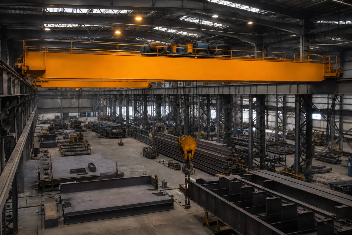
The primary horizontal structural beam of an overhead crane that supports the trolley and hoist.

Representative product image. Confirm appearance and specifications with the manufacturer.

Product Specifications

Technical details and manufacturing context for Bridge Girder

Definition
The bridge girder is the main horizontal structural component of a material handling crane that spans the working area. It provides the track for the trolley to travel along and supports the entire load being lifted. As part of the crane's bridge structure, it connects to the end trucks at both ends and must withstand bending moments, shear forces, and torsional stresses during operation. The girder is typically fabricated from structural steel or high-strength low-alloy steel, with material grades such as Q235B to Q355B, depending on span and capacity requirements. Standard spans range from 7.5 to 31.5 meters, with custom spans up to 40 meters, and rated lifting capacities from 5 to 100 tonnes, with higher capacities requiring a twin girder design. The crane duty class, from A5 to A7, indicates the intended service intensity, with A7 for heavy continuous use. Maximum deflection at rated load is limited to L/800 (where L is the span in mm) to ensure proper alignment and performance. Girder height typically ranges from 500 to 2000 mm, and width from 300 to 800 mm, depending on span and capacity. The weight per girder ranges from 2 to 20 tonnes, affecting the crane's deadload. Surface treatment includes blast cleaning to Sa2.5 per ISO 8501-1, followed by paint thickness of 80–120 μm for C3 corrosion environments per ISO 12944. Operating temperature range is -20°C to 60°C; below -20°C, low-temperature steel is required. Rail types P18 to P50 are matched to wheel loads. These specifications are reference ranges per GB/T 14405 and GB/T 3811; verify model-specific values with the manufacturer.
Working Principle
The bridge girder functions as a simply supported beam that transfers the weight of the trolley, hoist, and lifted load to the end trucks and ultimately to the runway structure. Its structural design ensures sufficient stiffness and strength to maintain proper alignment and prevent excessive deflection under maximum rated loads. The girder's cross-section, typically box-shaped, resists bending and torsional stresses. During operation, the trolley moves along rails mounted on the girder, and the girder must accommodate dynamic loads and impact. The deflection limit of L/800 ensures that the crane operates smoothly and safely. The girder's material and dimensions are selected based on span, capacity, and duty class to meet strength and stiffness requirements. Proper installation and alignment of the girder with end trucks are critical for load distribution and crane stability.
Common Materials
Structural steel, High-strength low-alloy steel
Technical Parameters
ParameterTypical rangeNotes & selection driver
Span Length7.5–31.5 mStandard spans; custom up to 40 mGB/T 14405
Rated Lifting Capacity5–100 tHigher capacities require twin girder designGB/T 14405
Crane Duty ClassA5–A7A7 for heavy continuous useGB/T 3811
Max Deflection≤L/800 mmAt rated load; L is span in mmGB/T 14405
Material GradeQ235B–Q355BHigher strength for longer spansGB/T 700, GB/T 1591
Girder Height500–2000 mmDepends on span and capacity
Girder Width300–800 mmBox girder width
Weight2–20 tPer girder; affects crane deadload
Surface TreatmentSa2.5Blast cleaning before primerISO 8501-1
Paint Thickness80–120 μmFor C3 corrosion environmentISO 12944
Operating Temperature-20–60 °CBelow -20°C requires low-temp steel
Rail TypeP18–P50Matched to wheel loadGB/T 11264

Ranges are indicative industry figures for RFQ preparation, not a supplier commitment. Confirm every value and standard with the legal manufacturer before ordering.

Components / BOM
  • Top Flange Part
    Provides compression resistance and supports trolley rails
    Material: steel
  • Web Plate Part
    Resists shear forces and connects top and bottom flanges
    Material: steel
  • Bottom Flange Part
    Provides tension resistance and completes the beam section
    Material: steel
  • Stiffeners Part
    Prevents web buckling and provides lateral support
    Material: steel

Applied To / Applications

This component is essential for the following industrial systems and equipment:

Industrial Ecosystem & Supply Chain Structure

Complementary Systems
Downstream Applications
Specialized Tooling

Application Fit & Sizing Matrix

Operational Limits
pressure: N/A (structural load bearing, not fluid pressure)
other spec: Max dynamic load capacity: 1-500 tons, Span: 5-50 meters, Deflection limit: L/800 to L/1000
temperature: -20°C to +60°C
Media Compatibility
✓ Indoor manufacturing facilities ✓ Warehouse material handling ✓ Shipyard assembly areas
Unsuitable: Marine splash zones with continuous saltwater exposure
Sizing Data Required
  • Maximum lifting capacity (tons)
  • Bridge span length (meters)
  • Operating duty cycle (CMAA class A-F)

Reliability & Engineering Risk Analysis

Failure Mode & Root Cause
Fatigue cracking
Cause: Cyclic loading from traffic, wind, and thermal expansion exceeding material endurance limits, often initiating at weld defects or stress concentrations.
Corrosion-induced section loss
Cause: Exposure to de-icing salts, marine environments, or industrial pollutants leading to rust formation, pitting, and reduced load-bearing capacity, especially in areas with inadequate drainage or compromised protective coatings.
Maintenance Indicators
  • Visible rust staining or spalling concrete exposing rebar, indicating active corrosion and loss of structural material.
  • Audible cracking or popping sounds under load, suggesting crack propagation or connection failure requiring immediate inspection.
Engineering Tips
  • Implement regular non-destructive testing (e.g., ultrasonic, magnetic particle) to detect subsurface cracks and corrosion before visible signs appear, prioritizing high-stress zones and weldments.
  • Enhance corrosion protection through cathodic protection systems, high-performance coatings, and improved drainage design to prevent water and contaminant accumulation on critical surfaces.

Indicative industry ranges for design and RFQ preparation. Confirm the exact figures and applicable standard with the manufacturer before specifying.

Compliance & Manufacturing Standards

Applicable Standards
ISO 10721-1: Steel structures - Part 1: Materials and design ASTM A709/A709M: Standard Specification for Structural Steel for Bridges EN 1090-2: Execution of steel structures and aluminium structures - Part 2: Technical requirements for steel structures

Quoted from the published standard.

Manufacturing Precision
  • Length: +/- 10 mm per 10 m
  • Web/flange thickness: +/- 1.5 mm
Quality Inspection
  • Ultrasonic Testing (UT) for internal defects
  • Dimensional verification with laser scanning

Manufacturers of Bridge Girder

3 companies list this product among what they make. Company figures are quoted from each company's own website; every card states where the relationship came from.

DGCRANE
Henan, CN
Listed on the company's own website · profile compiled by CNFX from public sources
ESC Steel Structures
Shanghai, CN
Listed on the company's own website · profile compiled by CNFX from public sources
Huasui Crane
Henan, CN
Also makes: Overhead Crane, Gantry Crane, Hoist Winch and 2 more
Listed on the company's own website · profile compiled by CNFX from public sources

Manufacturer listings support early research and capability understanding. They are not certification, ranking, or transaction guarantees.

Technical documentation
Request current drawings, revision history, and a signed specification sheet.
Manufacturing capability
Verify equipment lists, process limits, capacity, and representative production evidence.
Inspection readiness
Confirm test methods, calibrated equipment, sampling plans, and traceable reports.
Supplier transparency
Check the legal entity, factory address, ownership, certifications, and direct contacts.

CNFX does not score or rank suppliers. Buyers must verify all claims and documents with the legal manufacturer before ordering.

Supply Chain Compatible Machinery & Devices

Heavy-Duty CNC Plasma Cutting Machine

The Heavy-Duty CNC Plasma Cutting Machine is a standalone industrial device designed for cutting conductive metals such as steel, stainless steel, aluminum, and copper alloys.

Explore Specs →
Automated Powder Coating System

Integrated industrial system for applying dry powder coatings to metal substrates.

Explore Specs →
Centrifugal Pump Impeller

The centrifugal pump impeller is a critical rotating component that converts mechanical energy from the motor into kinetic energy in fluid systems.

Explore Specs →
High-Precision CNC Laser Cutting Machine

Computer-controlled industrial machine using focused laser beams to cut sheet metal with micron-level accuracy.

Explore Specs →

Frequently Asked Questions

What is the typical span range for a bridge girder?

Standard spans range from 7.5 to 31.5 meters, with custom spans up to 40 meters, per GB/T 14405. The actual span depends on the crane's application and runway layout.

What materials are commonly used for bridge girders?

Bridge girders are typically made of structural steel or high-strength low-alloy steel, with material grades such as Q235B to Q355B. The choice depends on span, capacity, and operating conditions.

How is the maximum deflection of a bridge girder specified?

The maximum deflection at rated load is limited to L/800, where L is the span in millimeters, per GB/T 14405. This ensures proper alignment and safe operation.

What standards apply to bridge girders?

Key standards include GB/T 14405 for general specifications, GB/T 3811 for design rules, and ISO 8501-1 and ISO 12944 for surface treatment and painting. Always verify compliance with the manufacturer.

Data Basis

Editorial classification, named public sources where available, and source-reviewed manufacturer records.

Preliminary Technical Classification
This page supports structured research, RFQ preparation, and supplier evaluation. It does not replace buyer-led supplier qualification, standards review, or technical approval.
Buyer enquiry

Request manufacturing insight for Bridge Girder

Ask for use case, specification boundaries, supplier type, and RFQ preparation information for this product.

Where it goes
Straight to the CNFX editorial desk, and to the manufacturer if this product is linked to a claimed profile. Nothing is broadcast to a supplier list.
Your details stay here
We do not sell or rent enquiry data, and we do not add you to a mailing list. Used only to answer this request.
No commission, no middleman
CNFX is a directory. We take no cut of any order and never negotiate on a supplier's behalf.
What we don't claim
A listing is not an endorsement. Qualify every supplier and verify every figure yourself before ordering.

Your business information is used only to process this request.

Thank you! Your message has been sent. We'll respond within 1–3 business days.
Sorry, we couldn't send your message. Please try again, or email us at contact@cnfx.com.

Need to Manufacture Bridge Girder?

Compare manufacturer profiles with relevant product and process capability.

Previous Product
Z-axis Ram/Spindle
Last Product
Get QuotesChat