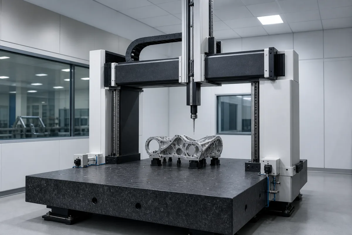
The bridge of a moving-bridge CMM is the beam and its two uprights that carry the Y carriage and Z ram across the table. This page is about what that beam is made of: granite, aluminium, 96% alumina or silicon carbide, and how each choice shows up as thermal growth that software cannot fully map out, as stiffness per kilogram of moving mass, and as the surface the air bearings ride on.
Covers the bridge beam and upright assembly of bridge-type CMMs as a structural part: material choice, thermal expansion and its compensation limits, stiffness-to-mass, hollow construction and guideway surfaces for air bearings. Selecting a whole CMM, its probing and its ISO 10360 acceptance belongs on Coordinate measuring machine (CMM); sub-micron reference machines are on High-accuracy reference bridge CMM for calibration and form measurement. Civil bridge steelwork and trench or manhole covers sold as a "bridge structure" are outside this page.
CNFX editorial research · Sources checked October 12, 2026 · 3 sources
Saint-Gobain's metrology flyer lists the four properties that decide a bridge beam in one table. The figures are the supplier's nominal values; grade and process can shift them.
Aluminium and granite sit close on specific stiffness (26 against 21–32) but far apart on expansion (22.5 against 5–7). The silicon carbide grades combine the low expansion of granite with three to five times its specific stiffness; SiSiC at 117 is 117/26 ≈ 4.5 times aluminium (Editorial calculation).
Conductivity pulls the other way. Granite at 3 W/m·K is slow to reach a uniform temperature, while aluminium at 204 and SiSiC at 140 even out quickly. A beam that expands little but equalises slowly can still hold a gradient between its top and bottom faces.
The flyer states that its SiC grades are about 20% lighter, about 25% higher in specific stiffness and about 50% lower in expansion than traditional ceramic, and that Saint-Gobain supplies beams for CMM bridges, Z-axis guide rails and air-bearing stages. Those percentages compare SiC with alumina, not with aluminium.
Material
Density g/cm³
Specific stiffness ×10⁶ m²/s²
Thermal conductivity W/m·K
Thermal expansion ×10⁻⁶/K
Granite
2.8–2.9
21–32
3
5–7
Alumina
3.9
96
20
8
Steel
7.8
27
47
12
Aluminium
2.6
26
204
22.5
Nitride-bonded SiC (NSiC)
2.8
86
20
4.4
Siliconized SiC (SiSiC)
3.0
117
140
4.5
Sintered SiC (SSiC)
3.1
132
125
4.0
Two sources give different numbers for the same materials: American Machinist quotes 96% alumina at 6 and aluminium at 23 ×10⁻⁶/°C, Saint-Gobain lists alumina at 8 and aluminium at 22.5. Ask for the grade-specific value of the beam actually offered.
02
Thermal growth the error map cannot remove
Walter Pettigrew's American Machinist article (April 2000) explains why a low expansion coefficient matters more than the software correction suggests.
The table is an Editorial calculation: length × coefficient × temperature change, assuming the whole beam changes temperature evenly.
Pettigrew's point is that the even case is the only one software handles. Linear growth can be compensated if the coefficient is known and the material is homogeneous. In practice the coefficient varies from batch to batch, controlled at best to ±10%; for aluminium that leaves ±2.3 parts per million uncertain, which on a 1,000 mm beam is ±2.3 µm per degree (Editorial calculation).
Beyond that, a real beam has gradients along its length and between inside and outside, castings and fabrications carry internal stress, and the room temperature keeps moving. The article concludes that components expand in a nonlinear manner, the structure bends, and error-mapping that assumes linear growth cannot control it. Its remedy is to start with the smallest expansion coefficient that weight and cost allow.
Beam material (Saint-Gobain value)
Length change of a 1,000 mm beam per 1 °C
Over a 2 °C swing
Aluminium, 22.5 ×10⁻⁶/K
22.5 µm
45 µm
Steel, 12 ×10⁻⁶/K
12 µm
24 µm
Alumina, 8 ×10⁻⁶/K
8 µm
16 µm
Granite, 5–7 ×10⁻⁶/K
5–7 µm
10–14 µm
SiSiC, 4.5 ×10⁻⁶/K
4.5 µm
9 µm
Ask how the builder compensates temperature on the bridge: number of sensors on the beam, whether compensation is linear only, and the temperature range and gradient limits (per hour, per metre) under which the stated accuracy holds.
03
Moving mass, stiffness and hollow sections
The bridge travels on every X move, so its mass sets acceleration while its stiffness sets how repeatably the probe returns to a point.
Pettigrew records that the industry moved away from granite bridges and columns in the early 1990s. Some builders went to aluminium, cheaper and lighter, giving fast measuring cycles; others went to ceramic, costlier and heavier but more stable. He quotes a stiffness-to-mass rating of 8.18 for 96% alumina against 2.52 for aluminium, a ratio of 8.18/2.52 ≈ 3.2 (Editorial calculation), and ties a stiffer bridge directly to more repeatable machine performance.
Steve Meredith's Quality Digest buyer's guide (January 1999) names the bridge, the bearings and the Z-axis bar as the parts that directly decide measuring and motion accuracy. It says a good share of builders use aluminium for light weight, machinability and lower cost, while granite or ceramic are better for thermal stability; it adds that aluminium expands nearly four times as much as granite, that granite damps vibration well and takes a fine bearing finish, and that granite's drawback for a moving bridge is weight.
The answer described there is hollow construction. Starrett's Hollow Granite Technology assembles granite plates and beams into hollow members that weigh like aluminium while keeping granite's thermal behaviour, used for both the bridge and its supports. On the largest machines, where hollow granite is impractical, the same builder used hollow ceramic for the bridge.
Design route
What it gains
What it gives up
Solid granite bridge
Low expansion, good damping, fine bearing surface
Moving mass; slow to equalise temperature
Aluminium bridge
Low cost, light, fast cycles, easy to machine
High expansion; soft surface needs hardening or coating
96% alumina bridge
Low expansion, high stiffness-to-mass, lappable
Higher cost and weight than aluminium
Hollow granite or hollow ceramic
Granite or ceramic thermal behaviour at lower mass
Assembled joints; builder-specific
Silicon carbide beam
Lowest expansion in the table with highest specific stiffness
Ask for cost, size limits and lead time
The last row's trade-off is a question for the supplier, not a sourced finding; neither article covers SiC cost.
04
Guideway surface and air-bearing gap
The bridge faces are also the guideways the air bearings fly on, so the material has to be ground and lapped flat.
Pettigrew notes that ceramic can be lapped and ground directly. Aluminium is soft and must first be hardened, by flame-spraying a hard layer or coating it with ceramic, which leaves a composite with two expansion rates that can distort the surface.
Meredith describes air bearings as having no contact with the surface during use, so no wear, and no moving parts. He recommends porous graphite bearing pads, which spread air through the material's own porosity and run a film of about 0.0002 in (about 5 µm, Editorial conversion). He gives 0.0010 to 0.0030 in (about 25–76 µm) as the air-gap range of conventional ported aluminium bearings, and says the smaller gap reduces bounce on the air cushion and gives a more rigid, accurate and repeatable machine.
Request the flatness specification of each bridge guideway face, the bearing type and air-gap value, and the supply-air quality the bearings need.
05
What to send when asking about a CMM bridge
Paste it into your enquiry below or into an email to a maker, then replace every bracket.
State the measuring range and the length of the bridge beam, the room temperature band and allowable gradient, and the target length-measuring error. Ask the builder to name the beam and upright material and grade with its expansion coefficient, whether members are solid or hollow, how many temperature sensors sit on the bridge and whether compensation is linear only, the guideway finish and flatness, and the air-bearing type and gap.
Explore company information and manufacturing capabilities, then discuss the scope of your project with a relevant supplier.
Share this page
Compiled and source-reviewed by the CNFX editorial team.
Each manufacturer above links to the page on that company's own website where the product is listed, with the date we checked it. How we source and review
· Page last updated 13 October 2026
Buyer questions
Is a granite bridge better than an aluminium one?
For thermal stability, yes: Saint-Gobain lists granite at 5–7 and aluminium at 22.5 ×10⁻⁶/K, and Quality Digest says aluminium expands nearly four times as much. Granite's drawback is weight on a moving bridge, which is why hollow granite and aluminium bridges exist. [1][3]
Can software compensate an aluminium bridge for temperature?
Only the linear, even part. American Machinist explains that coefficient uncertainty (±10%, so ±2.3 ppm for aluminium), gradients and internal stress make the beam grow nonlinearly and bend, which linear error maps cannot correct. [2]
Why use silicon carbide for a CMM beam?
Saint-Gobain's figures put SiSiC at 4.5 ×10⁻⁶/K expansion and 117 ×10⁶ m²/s² specific stiffness, against 22.5 and 26 for aluminium, at a density of 3.0 g/cm³. [1]
What air gap do CMM air bearings run at?
Quality Digest cites about 0.0002 in for porous graphite bearings and 0.0010–0.0030 in for conventional ported aluminium bearings, and says the smaller gap gives a stiffer, more repeatable machine. [3]
Sources and what still needs a direct check
Sources checked 2026-10-12. Three publishers: a ceramic supplier's property table, and two trade-press articles on CMM construction.