Editorial Technical Reference

Cable Management System

This page explains how Cable Management System is classified within Machinery and Equipment Manufacturing. Technical values and manufacturer relationships are research references; confirm the current specification and supplier evidence for each order.

Technical Definition & Core Assembly

A system designed to organize, route, protect, and secure electrical cables and wiring within robotic manipulators.
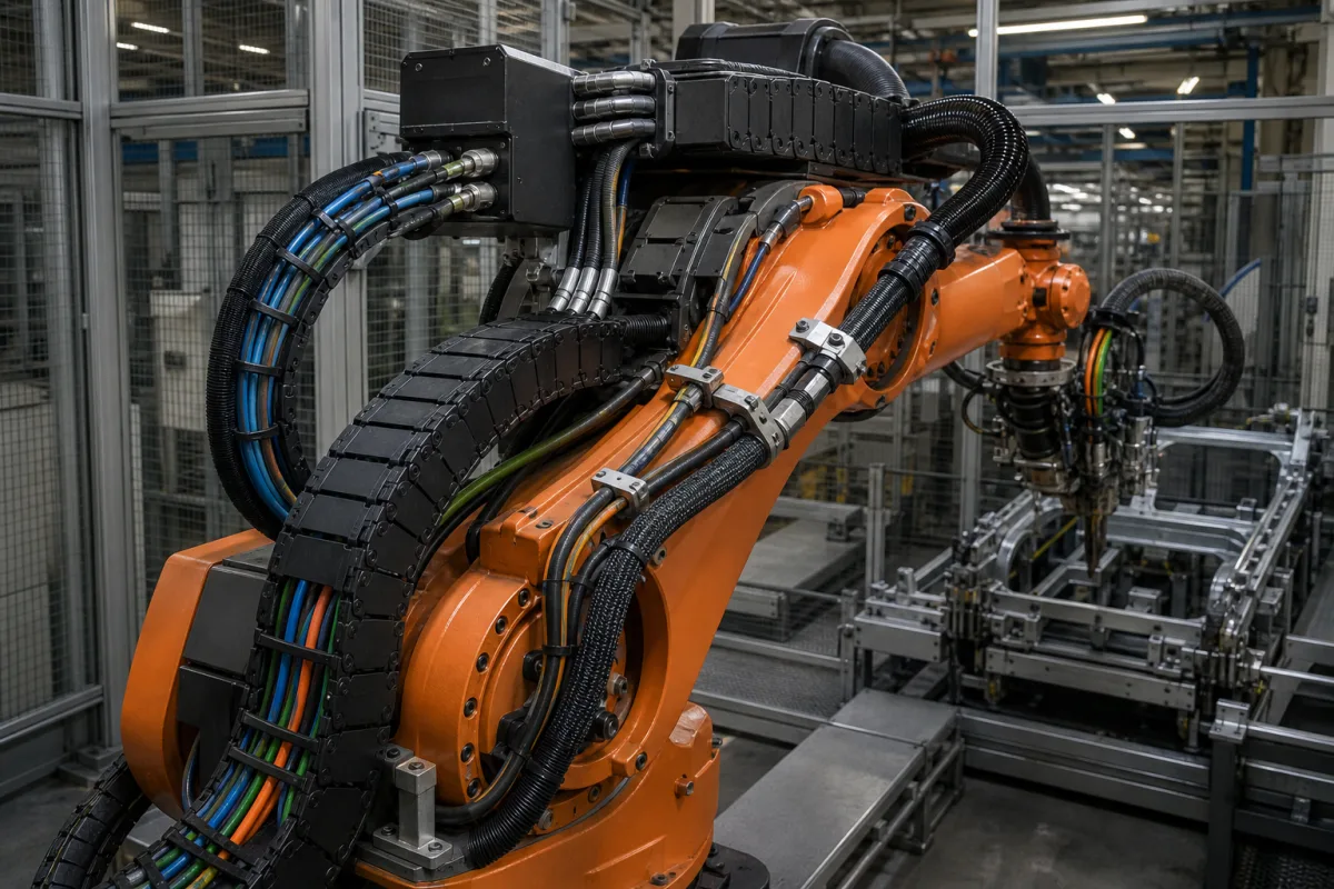
Representative product image. Confirm appearance and specifications with the manufacturer.

Product Specifications

Technical details and manufacturing context for Cable Management System

Definition
A specialized component of robotic manipulators that manages the routing, protection, and organization of power, signal, and data cables throughout the robotic arm structure. It prevents cable entanglement, reduces wear and tear, ensures reliable electrical connections, and maintains safety by keeping cables away from moving parts and hazardous areas. The system uses various components like cable carriers, conduits, clamps, and strain relief devices to guide cables along predetermined paths. It accommodates the repetitive bending and flexing motions of robotic joints while maintaining cable integrity and preventing interference with the manipulator's mechanical operations. Typical materials include engineering plastics (e.g., nylon, polyurethane), stainless steel, and aluminum alloy. Key parameters include number of cable channels (4–12), cable diameter range (4–20 mm), bending radius (50–200 mm), maximum cable weight (5–20 kg/m), operating temperature (-40–85 °C, per IEC 60068-2-14), ingress protection rating (IP54–IP65, per IEC 60529), material grade (6061-T6, per ASTM B221), surface treatment (anodized, per MIL-A-8625), weight (1.5–3.5 kg/m), tensile strength (310–350 MPa, per ASTM B221), maximum acceleration (10–20 m/s²), and mounting orientation (0–360°). These values are reference ranges; verify model-specific values and standards with the legal manufacturer or supplier.
Working Principle
The system uses various components like cable carriers, conduits, clamps, and strain relief devices to guide cables along predetermined paths. It accommodates the repetitive bending and flexing motions of robotic joints while maintaining cable integrity and preventing interference with the manipulator's mechanical operations. The design must match the cable diameter range and bending radius to avoid damage. The system's weight and tensile strength affect robot payload and inertia. Operating temperature and ingress protection ratings define environmental limits. Mounting orientation flexibility allows integration into various robot configurations. Proper selection requires considering cable weight, acceleration, and required number of channels. Maintenance signals include visible wear, cable abrasion, or restricted motion. Failure boundaries include exceeding bending radius, temperature, or acceleration limits, which can cause cable damage or system failure.
Common Materials
Engineering plastics (e.g., nylon, polyurethane), Stainless steel, Aluminum alloy
Technical Parameters
ParameterTypical rangeNotes & selection driver
Number of Cable Channels4–12 channelsDetermines cable capacity and routing flexibility.
Cable Diameter Range4–20 mmMust match the cables to be routed.
Bending Radius50–200 mmMinimum radius to prevent cable damage.
Maximum Cable Weight5–20 kg/mTotal weight the system can support per meter.
Operating Temperature-40–85 °CBeyond this range, materials may degrade.IEC 60068-2-14
Ingress Protection RatingIP54–IP65Protects against dust and water jets.IEC 60529
Material Grade6061-T6Aluminum alloy for strength and corrosion resistance.ASTM B221
Surface TreatmentAnodizedImproves wear and corrosion resistance.MIL-A-8625
Weight1.5–3.5 kg/mAffects robot payload and inertia.
Tensile Strength310–350 MPaWithstands pulling forces during motion.ASTM B221
Maximum Acceleration10–20 m/s²Higher acceleration may cause cable stress.
Mounting Orientation0–360 °Flexible mounting for various robot configurations.

Ranges are indicative industry figures for RFQ preparation, not a supplier commitment. Confirm every value and standard with the legal manufacturer before ordering.

Components / BOM
  • Cable Carrier
    Houses and guides cables through bending motions
    Material: Engineering plastic or metal
  • Mounting Brackets Part
    Secures the system to the robotic arm structure
    Material: Stainless steel or aluminum
  • Cable Clamps Part
    Secures cables at entry/exit points and prevents pull-out
    Material: Plastic or metal
  • Strain Relief Part
    Absorbs mechanical stress on cables at connection points
    Material: Rubber or flexible plastic
  • Cable Conduit
    Encloses cable runs that do not sit inside the carrier chain.

Applied To / Applications

This component is essential for the following industrial systems and equipment:

Industrial Ecosystem & Supply Chain Structure

Complementary Systems
Downstream Applications
Specialized Tooling

Application Fit & Sizing Matrix

Operational Limits
pressure: Not applicable (non-pressurized system)
other spec: Cable bend radius ≥ 10× cable diameter, IP67 ingress protection rating
temperature: -40°C to +85°C
Media Compatibility
✓ Industrial lubricants (grease/oil) ✓ Coolant fluids (water-glycol mixtures) ✓ Hydraulic fluids (mineral-based)
Unsuitable: High-concentration acidic or caustic chemical environments
Sizing Data Required
  • Total number and diameter of cables to be routed
  • Required cable bend radius and routing path length
  • Robotic manipulator's range of motion and vibration levels

Reliability & Engineering Risk Analysis

Failure Mode & Root Cause
Insulation Degradation
Cause: Thermal cycling, chemical exposure, or UV radiation leading to embrittlement, cracking, and loss of dielectric properties.
Connector Corrosion/Loose Connections
Cause: Environmental ingress (moisture, contaminants), vibration-induced fretting, or improper installation causing increased resistance and potential arcing.
Maintenance Indicators
  • Visible cable jacket cracking, discoloration, or swelling indicating material breakdown.
  • Audible arcing, intermittent signal loss, or abnormal heat detected at connection points.
Engineering Tips
  • Implement proper cable routing with adequate bend radius protection and strain relief to minimize mechanical stress.
  • Use environmental sealing at connections and apply protective conduits or trays in corrosive or high-traffic areas.

Indicative industry ranges for design and RFQ preparation. Confirm the exact figures and applicable standard with the manufacturer before specifying.

Compliance & Manufacturing Standards

Applicable Standards
ANSI/TIA-942-B - Telecommunications Infrastructure Standard for Data Centers CE Marking - Conformity with EU Directives (e.g., Low Voltage Directive 2014/35/EU)

Quoted from the published standard.

Manufacturing Precision
  • Cable Bend Radius: +/- 5% of specified minimum radius
  • Mounting Hole Alignment: +/- 0.5mm from datum
Quality Inspection
  • Visual and Dimensional Inspection per Engineering Drawings
  • Flammability Test (e.g., UL 94, IEC 60695-11-10) for Plastic Components

Manufacturers of Cable Management System

Manufacturer profiles associated with Cable Management System.

Sourcing Cable Management System from China?
Tell us your specification and target quantity — we will match it against manufacturer records and come back with the factories that fit.
Request manufacturers We manufacture this

Manufacturer listings support early research and capability understanding. They are not certification, ranking, or transaction guarantees.

Technical documentation
Request current drawings, revision history, and a signed specification sheet.
Manufacturing capability
Verify equipment lists, process limits, capacity, and representative production evidence.
Inspection readiness
Confirm test methods, calibrated equipment, sampling plans, and traceable reports.
Supplier transparency
Check the legal entity, factory address, ownership, certifications, and direct contacts.

CNFX does not score or rank suppliers. Buyers must verify all claims and documents with the legal manufacturer before ordering.

Supply Chain Compatible Machinery & Devices

Heavy-Duty CNC Plasma Cutting Machine

The Heavy-Duty CNC Plasma Cutting Machine is a standalone industrial device designed for cutting conductive metals such as steel, stainless steel, aluminum, and copper alloys.

Explore Specs →
Automated Powder Coating System

Integrated industrial system for applying dry powder coatings to metal substrates.

Explore Specs →
Centrifugal Pump Impeller

The centrifugal pump impeller is a critical rotating component that converts mechanical energy from the motor into kinetic energy in fluid systems.

Explore Specs →
High-Precision CNC Laser Cutting Machine

Computer-controlled industrial machine using focused laser beams to cut sheet metal with micron-level accuracy.

Explore Specs →

Frequently Asked Questions

What is the primary function of a cable management system in a robotic manipulator?

It organizes, routes, protects, and secures electrical cables and wiring within the robotic arm, preventing entanglement, reducing wear, and ensuring reliable connections.

What materials are commonly used for cable management systems?

Engineering plastics (e.g., nylon, polyurethane), stainless steel, and aluminum alloy are typical materials, chosen for strength, flexibility, and corrosion resistance.

How do I select the right cable management system for my robot?

Consider the number of cable channels, cable diameter range, bending radius, maximum cable weight, operating temperature, ingress protection, and mounting orientation. Verify these parameters against your robot's specifications.

What standards apply to cable management systems?

Relevant standards include IEC 60068-2-14 for temperature, IEC 60529 for ingress protection, ASTM B221 for aluminum alloy, and MIL-A-8625 for anodizing. These are references for verification, not proof of compliance.

Data Basis

Editorial classification, named public sources where available, and source-reviewed manufacturer records.

Preliminary Technical Classification
This page supports structured research, RFQ preparation, and supplier evaluation. It does not replace buyer-led supplier qualification, standards review, or technical approval.
Buyer enquiry

Request manufacturing insight for Cable Management System

Ask for use case, specification boundaries, supplier type, and RFQ preparation information for this product.

Where it goes
Straight to the CNFX editorial desk, and to the manufacturer if this product is linked to a claimed profile. Nothing is broadcast to a supplier list.
Your details stay here
We do not sell or rent enquiry data, and we do not add you to a mailing list. Used only to answer this request.
No commission, no middleman
CNFX is a directory. We take no cut of any order and never negotiate on a supplier's behalf.
What we don't claim
A listing is not an endorsement. Qualify every supplier and verify every figure yourself before ordering.

Your business information is used only to process this request.

Thank you! Your message has been sent. We'll respond within 1–3 business days.
Sorry, we couldn't send your message. Please try again, or email us at contact@cnfx.com.

Need to Manufacture Cable Management System?

Compare manufacturer profiles with relevant product and process capability.

Previous Product
Cabin
Next Product
Calibration Module
Get QuotesChat