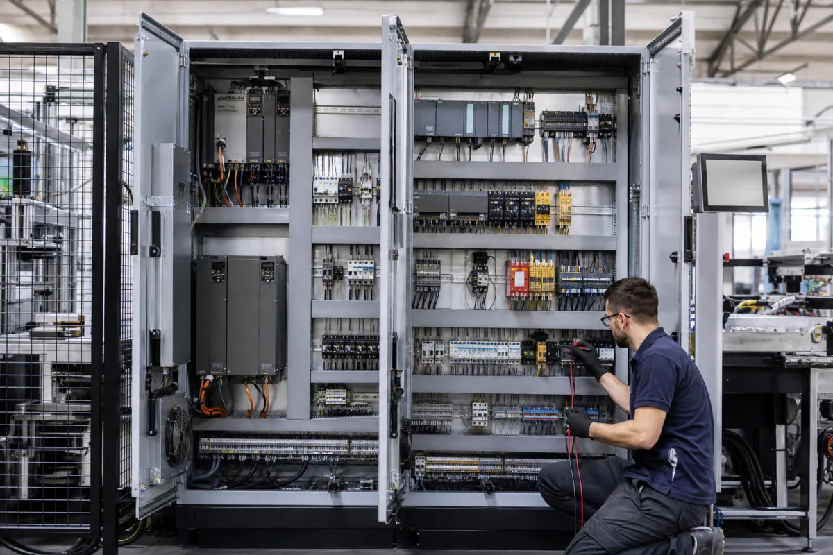
Central control cabinet for a machining cell: safety relays, cell-wide supply duties and the clear space in front of it
The one cabinet that powers and supervises a guarded machining or robot cell · E-STOP and guard-door safety relays, IEC 60204-1 Edition 6 duties for the whole cell's equipment, and the working space it needs in front
In a cell where CNC machines, a robot and conveyors work behind one fence, the electrical equipment is gathered into a central cabinet set at the edge of the guarding: one bay for the drives, one for the controller, safety relays, terminals and power distribution, and an operator panel nearby. This page deals with what is particular to that central position — the safety circuits that stop the whole cell when an E-STOP is pressed or a guard door opened, the IEC 60204-1 duties that apply to everything the cabinet feeds, and the space it needs around it on the shop floor.
Central control cabinets that feed and supervise a whole machining, robot or assembly cell from one point: cell-level E-STOP and guard-door safety relays, IEC 60204-1 duties at the cell infeed and for service sockets, and floor working space in front of the cabinet. Enclosure IP rating, heat rise and SCCR calculation for any machine or process control cabinet are covered on the Control cabinet page; wiring segregation, grounding and noise inside PLC panels on the PLC control panel page; controller mounting space and 24 V DC control power on the PLC control cabinet page; the fence and interlocked doors themselves on the Machine and robot cell safety guarding page; line-level control of body-in-white welding lines on the Central control system for robotic body-in-white welding lines page.
CNFX editorial research · Sources checked October 12, 2026 · 3 sources
Stopping the whole cell: E-STOP and guard-door circuits on a safety relay
Pilz's PNOZ X2.8P is one example of the relay that sits in a cell cabinet between the E-STOP buttons or safety-gate switches and the contactors that cut power to the drives. It has three positive-guided safety contacts (N/O) and one auxiliary contact (N/C), connects E-STOP pushbuttons, safety-gate limit switches, light guards and a start button, and is listed for PL e of EN ISO 13849-1 and SIL CL 3 of IEC 62061 in a 22.5 mm housing. [1]
With the input circuit closed the three safety contacts are closed and the auxiliary contact is open; when an E-STOP is pressed the safety contacts open redundantly and the auxiliary contact closes, which can be wired to the PLC as a status signal. [1]
Editorial calculation: a contact rated 6 A on its own is good for only 3.5 A when all three contacts of the 24 V unit carry load on an AC supply — 58% of the single-contact figure. Three contactor coils on one relay are within that, but a cell cabinet that tries to switch drive enable, robot power and conveyor power through the same three contacts at higher current needs a contact expansion module or a second relay. Pilz's catalogue states that one PNOZ is used per safety function, so a cell with an E-STOP circuit and a guard-door circuit has two. [1]
Editorial note: the 15–30 ms is only the relay's share of the stopping time; the drives' braking and the machine's run-down come after it and decide the guard distance.
List for the cabinet builder every stop function in the cell (E-STOPs, guard doors, light curtains, robot teach pendant enabling), which drives and contactors each must switch off, the stop category, and the PL or SIL from the risk assessment.
02
What IEC 60204-1 Edition 6 adds for a cabinet that feeds a whole cell
Siemens' white paper on Edition 6.0 of IEC 60204-1 (updated 2024) sets out the standard's reach: electrical equipment of machines not portable by hand, from the point where the supply connects to the machine's equipment, at up to 1,000 V AC and 1,500 V DC. It was published as an EN standard in November 2019 and the transition period ended on 14 September 2021. [2]
Siemens adds that, for handheld Class I equipment, the disconnection time in Table A.1 is 0.4 s at U0 = 230 V. [2] Editorial note: in a cell cabinet the drive bay feeds every axis and spindle motor of the cell through frequency converters, so the PDS clause applies to each axis and spindle drive; ask the cabinet builder for the verification record per drive rather than one record for the cabinet infeed.
Edition 6 change (per Siemens)
Effect in a central cell cabinet
New clause 7.10: short-circuit current rating of the electrical equipment
All equipment, not only the infeed protection, must suit the minimum and maximum short-circuit current at the machine's infeed; design rules, calculation or tests are allowed, by IEC 61439-1, IEC 60909-0 and related methods [2]
Clause 15.1: RCDs
Socket outlet circuits up to 20 A now need RCDs of IΔn ≤ 30 mA — for example service sockets in the cabinet door or on the cell [2]
Clause 18.2.3: motors on power drive systems
Fault loop impedance is tested at the converter input terminals, using the converter maker's data [2]
Clause 17: documentation
Revised to necessary documents; Annex I table assigns each type of information to a recommended standard [2]
03
Clear floor space in front of the cabinet: 0.9 to 1.2 m deep, full width, doors open to 90°
A central cabinet beside a cell fence competes for floor space with conveyors, chip bins and walkways. In the United States, OSHA 29 CFR 1910.303(g) sets the working space in front of equipment of 600 V or less that may be examined, adjusted or serviced while energised. [3]
Condition A has exposed live parts on one side only; B has live parts on one side and grounded parts on the other; C has exposed live parts on both sides with the worker between. Depth is measured from the enclosure front or opening when live parts are enclosed. [3]
The width of the working space must be the width of the equipment or 762 mm (30 in), whichever is greater, and must let doors and hinged panels open to at least 90°. Other equipment above or below may project no more than 153 mm (6 in) into it, the space may not be used for storage, and headroom for installations built on or after 13 August 2007 is 1.98 m (6.5 ft). [3]
Editorial calculation: a two-bay cabinet 1,600 mm wide on a 400 V three-phase supply (about 230 V to ground) with a grounded cell fence opposite falls in the 151–600 V row, Condition B, so it needs a clear area at least 1,600 mm wide and 1.0 m deep — 1.6 m² that conveyors and bins may not occupy — and its door leaves must still swing to 90° within it.
Mark the cabinet's working space on the cell layout before the guarding and conveyors are fixed, and state the supply voltage to ground and what stands opposite the cabinet.
04
What to send for a cell's central cabinet
Paste it into your enquiry below or into an email to a maker, then replace every bracket.
Cell: [machines, robot, conveyors fed from the cabinet; layout]
Supply: [voltage, frequency, earthing system; prospective short-circuit current at the infeed]
Stop functions: [E-STOPs, guard doors, light curtains; stop category; PL or SIL]
Drives: [number of axes and spindles; converter models]
Control: [PLC, HMI, network to machines and robot]
Service sockets: [number, rating, RCD]
Site: [floor space in front; door swing; ambient]
Documents: [IEC 60204-1 verification records; SCCR basis]
Explore company information and manufacturing capabilities, then discuss the scope of your project with a relevant supplier.
Share this page
Compiled and source-reviewed by the CNFX editorial team.
Each manufacturer above links to the page on that company's own website where the product is listed, with the date we checked it. How we source and review
· Page last updated 13 October 2026
Buyer questions
How fast does a safety relay drop out after an E-STOP?
Pilz gives 15 ms typical and 30 ms maximum for the 24 V PNOZ X2.8P, and 10 ms typical and 20 ms maximum for the 24–240 V version. [1]
Do service sockets in a control cabinet need an RCD?
Siemens says IEC 60204-1 Edition 6 requires RCDs of IΔn ≤ 30 mA for socket outlet circuits up to 20 A. [2]
How much space is needed in front of a control cabinet?
Under OSHA 1910.303, 0.9 m deep up to 150 V to ground and 0.9, 1.0 or 1.2 m from 151 to 600 V depending on what is opposite, at least 762 mm or the equipment's width, with doors opening to 90°. [3]
What voltage range does IEC 60204-1 cover?
Siemens states up to 1,000 V AC and 1,500 V DC, from the point of supply connection to the machine's electrical equipment. [2]
Sources and what still needs a direct check
Sources checked 2026-10-12. Safety relay data come from Pilz's PNOZ technical catalogue (2016-09, distributor-hosted copy); the Edition 6 changes to IEC 60204-1 from Siemens' white paper; working space from the OSHA electrical standard in the US eCFR.