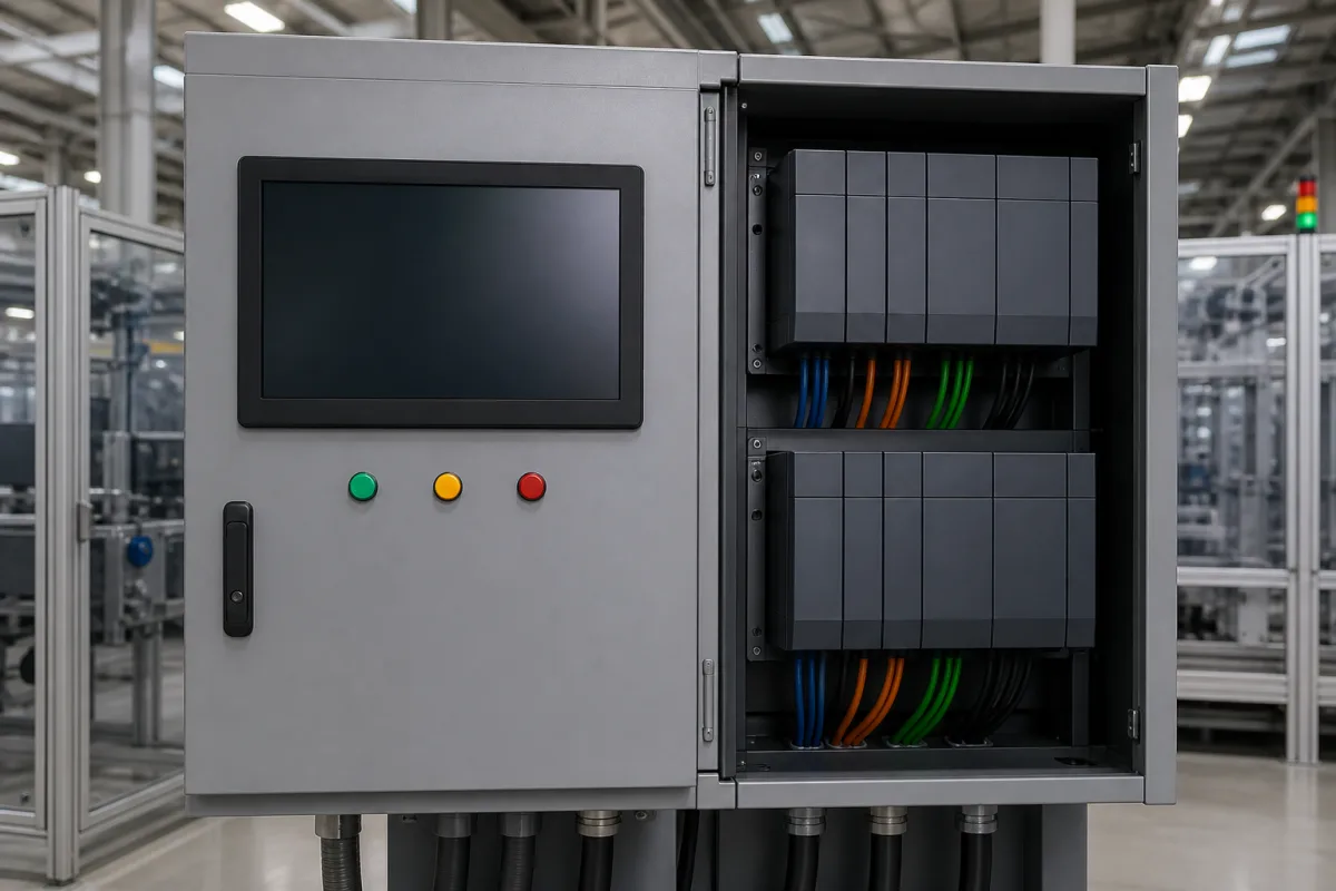
Central control unit for mechanical press and metal forming lines (clutch/brake, safety and die protection)
Press-line central control · Clutch/brake control reliability, brake monitoring, light-curtain safety distance and die-protection inputs for metal forming lines
A press-line central control unit is the cabinet that commands a mechanical press or forming line: it engages the clutch and applies the brake, accepts the stroke command only from approved operator stations, stops the slide when a light curtain is broken, watches the brake for wear and halts the press when die-protection sensors see a misfeed. Ask three things first: whether its control and brake monitoring meet the press rules where it will run, what stopping time and safety distance its guarding is based on, and how many operator stations, light curtains and die-protection inputs it takes.
Central clutch/brake, safety and die-protection control units for mechanical power presses and metal forming and stamping lines, supplied as a cabinet with HMI, processor, I/O and safety inputs. General industrial control systems (PLCs, CPUs, I/O modules and EtherCAT motion) are covered on the Industrial control systems page. Hydraulic press controls, press brakes, robot controllers and stand-alone safety light curtains are outside this page except where compared.
CNFX editorial research · Sources checked October 12, 2026 · 3 sources
OSHA's mechanical power press standard, 29 CFR 1910.217, defines control reliability as a control system built so that a failure within it does not prevent the normal stopping action, but does prevent initiation of a successive stroke until the failure is corrected. Its brake monitor must automatically prevent a successive stroke if stopping time or braking distance deteriorates to where the safety distance in use no longer meets the rule, and must indicate that deterioration. [1]
Where a presence-sensing device protects the operator, the rule requires it to be interlocked into the control circuit to prevent or stop slide motion while a hand is in the sensing field on the downstroke; it may not be used on full-revolution clutches, and muting is allowed only on the upstroke. For presses run in presence-sensing device initiation (PSDI) mode, the brake monitor setting may allow an increase of no more than 10% of the longest stopping time or 10 milliseconds, whichever is longer, and the control must permit only a single stroke per initiation command. [1]
Editorial calculation: for a press whose longest stopping time is 200 ms, 10% is 20 ms, which is longer than 10 ms, so the monitor may allow stopping time to grow to at most 220 ms before preventing the next stroke. The stopping time is an assumed example. [1]
Give the supplier the press type, tonnage and clutch/brake type, the operating modes (inch, single stroke, continuous, PSDI), the number of operator stations, light curtains and their response times, the measured stopping time, die-protection sensors and their logic, feed and transfer interfaces, the HMI and tool-memory needs, and the rules and standards the line must meet where it will be installed.
02
Set the safety distance from the press stopping time
OSHA requires the safety distance from a presence-sensing field to the point of operation to exceed Ds = 63 in/s × Ts, where 63 in/s is the hand-speed constant and Ts is the press stopping time measured at about 90° of crankshaft rotation. [1]
Keyence's guide to ISO 13855 gives S = K × T + 8(d − 14) for light curtains with resolution d ≤ 40 mm and K = 2,000 mm/s, where T is the machine's maximum stopping time plus the light curtain's response time; if S is 500 mm or more, it is recalculated with K = 1,600 mm/s and set to 500 mm if the new result is 500 mm or less. For 40 < d ≤ 70 mm it uses K = 1,600 mm/s and C = 850 mm, and S must be at least 100 mm. [2]
Editorial calculation: with a 0.2 s total stopping time and a 30 mm resolution curtain, ISO 13855 gives 2,000 × 0.2 + 8 × 16 = 528 mm; recalculated with 1,600 mm/s it is 448 mm, so S is set to 500 mm. OSHA's formula for the same 0.2 s gives 63 × 0.2 = 12.6 in (320 mm). The 0.2 s is an assumed example; a slower stop pushes guarding further from the die, which is why the brake monitor matters. [2][1]
03
Count the stations, curtains and die-protection inputs
Wintriss's WPC APEX clutch/brake control for mechanical power presses, announced for FABTECH 2025, is described with a touch-screen display, tool-number memory, four dedicated die-protection inputs, detailed self-diagnostics, and inputs for up to four operator stations and up to four Shadow light curtains. The Shadow 10 light curtain is described with an IP65 housing and a control box taking up to four transmitter/receiver pairs. [3]
Editorial note: list every operator station, curtain and die sensor the line needs before quoting, and ask how many more the controller accepts, because a line that outgrows four of each needs a different controller or an expansion.
04
Processor, safety I/O, brake monitor, die-protection inputs and HMI in the press cabinet
Two of these parts exist because of the press rule: the brake monitor and a processor built for control reliability; the die-protection inputs and HMI follow the Wintriss example.
Press control quotation: stopping time, monitor setting and I/O counts
The measured stopping time drives both the safety distance and the brake monitor setting, so ask for it with the quotation; I/O counts can be checked against the four-of-each Wintriss example.
Explore company information and manufacturing capabilities, then discuss the scope of your project with a relevant supplier.
Share this page
Compiled and source-reviewed by the CNFX editorial team.
Each manufacturer above links to the page on that company's own website where the product is listed, with the date we checked it. How we source and review
· Page last updated 13 October 2026
Buyer questions
What is control reliability on a press?
Under 29 CFR 1910.217, a failure in the control must not prevent normal stopping but must prevent the next stroke until corrected. [1]
How far must a light curtain be from the die?
OSHA uses 63 in/s × stopping time; Keyence's ISO 13855 guide uses 2,000 mm/s × total stopping time + 8(d − 14) for curtains up to 40 mm resolution. [1][2]
How many die-protection inputs does a press control have?
Wintriss's WPC APEX is described with four dedicated die-protection inputs and up to four operator stations and light curtains. [3]
Sources and what still needs a direct check
Sources checked 2026-10-12. 29 CFR 1910.217 is an OSHA regulation via eCFR; Keyence's page explains ISO 13855 for its light curtains; the Wintriss description is a maker announcement in Industrial Machinery Digest.