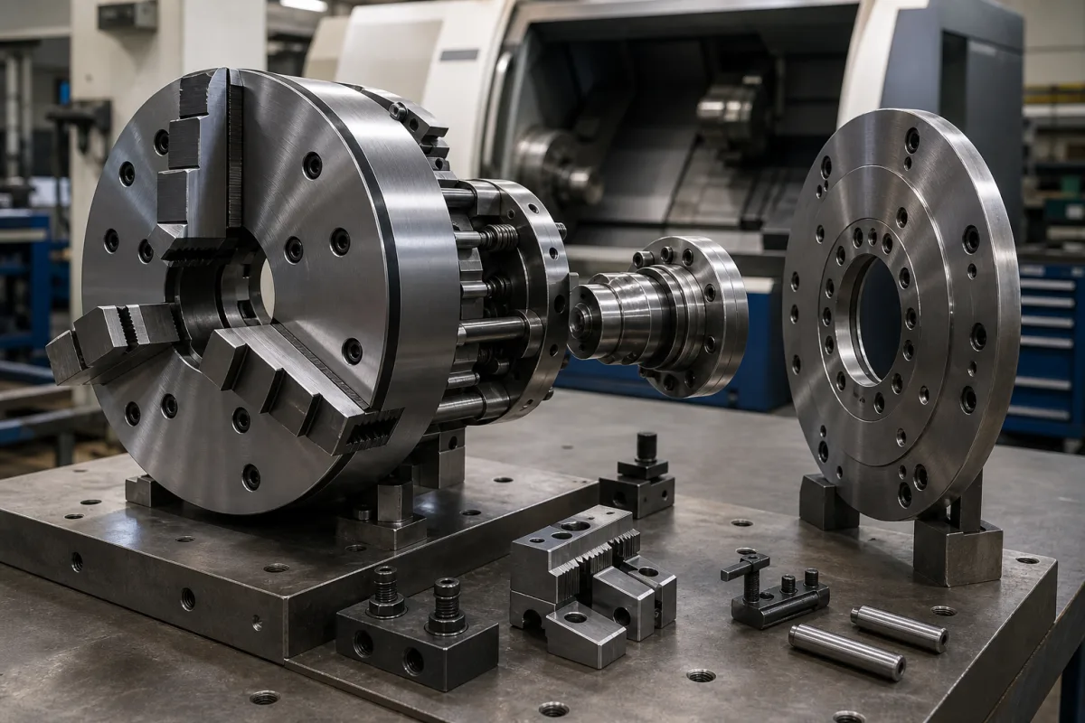
Hollow power chuck assembly for CNC lathes: chuck body, adapter plate and draw tube to the hydraulic cylinder, and the grip left at speed
The hollow power chuck on a CNC lathe spindle, with its adapter plate and the draw tube to a rotating hydraulic cylinder · bought for a through-hole and a speed, but judged by how much grip is left once the jaws are flung outward at full rpm
On a CNC lathe the workpiece is held by a power chuck bolted to the spindle nose through an adapter plate. A draw tube runs down the hollow spindle to a rotating hydraulic cylinder at the back of the headstock; when the cylinder pulls, a wedge or lever mechanism in the chuck body drives the jaws inward. Two things decide whether that assembly suits a job: the bar or tube that has to pass through it, and how much of the clamping force measured at standstill is still there when the spindle is at speed and the cut is pushing on the part.
Hydraulically actuated hollow (open-centre) power chucks for CNC lathes and turning centres, taken as an assembly with adapter plate, draw tube and rotating cylinder: through-hole, maximum and reference speed, static and dynamic clamping force, centrifugal compensation and the clamping force a cut needs. Base and top jaws are covered on the Lathe chuck jaw assembly page and the workpiece spindle on the Built-in motor rotary spindle for CNC lathes page. Cap-gripping chucks on bottle cappers are covered on the High-speed rotary bottle capping machine, Jaw-type capping head and Capping spindle pages.
CNFX editorial research · Sources checked October 13, 2026 · 4 sources
Centrifugal pull on the jaws rises with the square of rpm: why the DIN 6386 reference speed leaves one third of the grip
El-Dahabi, Jabbour and Abdulwahab give the centrifugal force of a rotating mass as F = m·r·(π·n/30)², with n in rpm and r the radius of its centre of mass, and note that CNC lathe spindles now reach up to 20,000 rpm, so centrifugal force on the chuck cams rises sharply and reduces clamping force. [2]
BERG Spanntechnik explains the speed limits used for power chucks. The recommended (reference) speed under DIN 6386 is the speed at which the calculated centrifugal force of the stated jaw type equals two thirds of the maximum clamping force at standstill, with top jaws stepped inward and not protruding beyond the chuck diameter; at that speed one third of the standstill clamping force is left to hold the workpiece, provided the chuck is in perfect condition. VDI 3106 can be used to determine permissible speed and the residual clamping force at a given speed. [1]
Editorial calculation, using the formula above with assumed values: a jaw set of 1.5 kg in total with its centre of mass at 50 mm radius produces 1.5 × 0.05 × (π × 2,500/30)² ≈ 5.1 kN of outward force at 2,500 rpm and four times that, about 20.6 kN, at 5,000 rpm. The jaw mass and radius here are assumptions for illustration, not data from the sources; heavier or taller top jaws, or jaws set further out, raise the loss in proportion. [2]
The Gabrovo authors analyse a counterweight on the opposite arm of each jaw lever as a way to balance the centrifugal force of the cam, and give the actuator force per cam as the cylinder pressure times its useful area times the efficiency of the hydraulic drive, which accounts for leakage and seal friction. [2] BERG adds that regular, careful lubrication of all sliding surfaces is a precondition for the chuck to work properly and avoids loss of clamping force and premature wear. [1]
Give the top-jaw type, mass and mounting radius, the spindle speed range, and the clamping force needed at that speed; ask the supplier for the clamping-force-against-speed curve for those jaws and the cylinder pressure it assumes.
02
Through-hole against speed: 26 mm at 8,000 rpm up to 166.5 mm at 2,000 rpm in two open-centre ranges
Kitagawa lists its BT200 two-jaw and BB200 large thru-hole open-centre power chucks by outside diameter, through-hole and maximum speed; at the four sizes listed in both, the BB200 has the larger bore and the same or a higher maximum speed.
Editorial calculation: across the BB200 range the through-hole rises from 53 mm to 166.5 mm, about 3.1 times, while maximum speed falls from 6,000 to 2,000 rpm; for the 8-inch size the large-bore version gains 14 mm of bore over the two-jaw chuck at the same 5,000 rpm. [3][4] The bar or tube still has to pass the draw tube and the cylinder behind it, so the smallest bore in the chuck, adapter plate, draw tube and cylinder sets the bar capacity of the assembly.
Maximum speed in these lists is a ceiling, not a working speed: the grip actually left at that speed depends on the jaws fitted and the actuating force, as the previous section shows. [1]
Chuck size
BT200 two-jaw: OD / through-hole / max speed
BB200 large thru-hole: OD / through-hole / max speed
State the bar or tube diameter to pass, the spindle nose and adapter plate, the cylinder model and its through-hole, and the maximum speed you will run.
03
How much grip the cut needs: tangential force, axial push and a safety factor
For turning an outer diameter, the Gabrovo paper sets the clamping force so that friction at the jaws resists both rotation of the part by the tangential cutting force Pz and its axial shift by the feed force, multiplied by a safety factor chosen for the conditions. [2]
The paper also lists centrifugal force on an off-centre workpiece and inertia during sudden speed changes as forces to include in certain cases. [2] Editorial note: comparing the clamping force a cut needs with the force left at speed, from the curve in the previous section, is the check that decides whether a chuck and cylinder assembly is large enough.
Cutting force component
Relative size given
Resisted by
Tangential Pz
Largest component; creates a moment that turns the part in the chuck [2]
Explore company information and manufacturing capabilities, then discuss the scope of your project with a relevant supplier.
Share this page
Compiled and source-reviewed by the CNFX editorial team.
Each manufacturer above links to the page on that company's own website where the product is listed, with the date we checked it. How we source and review
· Page last updated 13 October 2026
Buyer questions
Why does a lathe chuck lose grip at high speed?
Centrifugal force on the jaws, F = m·r·(π·n/30)², pulls them outward; it rises with the square of spindle speed and subtracts from the clamping force on an outside grip. [2]
What is the recommended speed of a power chuck?
Under DIN 6386, as BERG describes it, the speed at which calculated centrifugal force equals two thirds of standstill clamping force, leaving one third to hold the part. [1]
How large a bore can an open-centre power chuck have?
Kitagawa's BB200 large thru-hole range runs from 53 mm at 6,000 rpm to 166.5 mm at 2,000 rpm. [3]
Sources and what still needs a direct check
Sources checked 2026-10-13. Speed definitions are from BERG Spanntechnik's technical notes; the force relations from El-Dahabi et al., Journal of the Technical University of Gabrovo (2018); bore and speed ratings from Kitagawa's product listings.