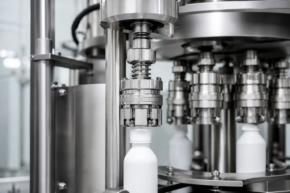
Jaw-type capping head for tamper-evident screw caps: the gripping chuck, its tamper-band flange and how each head is checked
The gripping end of a screw-capping head · pivoting jaws in a bell that close on the cap, a flange that stops the tamper band snapping its bridges, ejecting a cap that was never applied, and checking each head with an instrumented bottle
On a rotary screw capper, each head has two halves: an upper part that turns and lowers it and limits the torque, and a lower gripping part that holds the cap, carries it onto the bottle neck and turns it down the thread. The gripping part is what touches the closure, so it decides whether a tamper-evident cap goes on with its band intact, whether an unapplied cap is cleared before the next cycle, and how faithfully the set torque and top load reach the cap. This page is about that gripping end, in its jaw-type form, and the instruments used to check it head by head.
Cap-gripping assemblies of screw-capping heads — jaw-type chucks with pivoting jaws, serrated jaw inserts, tamper-band support flanges and cap ejectors — for one-piece tamper-evident plastic screw caps on beverage and food containers, and the instrumented test bottles used to check head torque and top load. The rotating spindle with its magnetic torque clutch, top-load spring and chuck carrier is covered on the Capping spindle page; complete rotary and inline screw cappers on the High-speed rotary bottle capping machine page; crown, ROPP and cork closing on the Automated bottle capping machine page. Closures themselves are outside this page.
CNFX editorial research · Sources checked October 12, 2026 · 5 sources
Pivoting jaws inside a bell: how the chuck closes on the cap
Alplast's patent application EP0248145 describes a typical jaw chuck at the bottom of a rotary, vertically reciprocating capping head. A bell-shaped driving member carries a set of jaws; the top of each jaw bears on the inside of the bell through a toroidal bead and is located by a drive pin screwed into the bell, so the bell turns the jaws with it. A central tubular element carried on a helical spring holds the jaws at their upper ends, and a rod with a stepped foot — cylindrical, conical, cylindrical — slides inside it. [1]
When the foot bears on the conical inner faces of the jaws, they tilt open about their fulcrum; as the chuck comes down over the cap and the foot moves relative to the jaws, they close around it. Each jaw has a replaceable insert, screwed on, with vertical serrations that engage the vertical serrations moulded on the cap's upper skirt, so torque passes through the ribs rather than by friction. [1] An earlier jaw design the patent cites, US 3,031,822, used jaws with an inward projection resting on top of the cap and an arcuate portion gripping its side wall. [1]
Editorial note: because the serrated insert is the part that wears and the part that must match the cap's rib pitch and diameter, it is the change part to list for every closure the line runs.
02
A flange under the lower skirt so the tamper band's bridges survive capping
A one-piece tamper-evident screw cap has an upper threaded skirt and a lower band joined by thin frangible bridges; a bead inside the band snaps under a collar on the bottle neck, and unscrewing breaks the bridges to show the pack was opened. Alplast explains why a plain jaw chuck can break them during capping: when the bead reaches the collar, the bridges collapse and the band is compressed against the upper skirt; when the bead then snaps over the collar, the sudden release stretches the bridges beyond their original length and they fail in tension. [1]
Its answer is a radially inward flange at the lower end of each jaw insert that sits under the lower skirt and forms an abutment for it, absorbing the forces as the bead rides over the collar. A tooth-shaped projection higher on each jaw has a flat lower face whose distance from the flange corresponds to the height of the cap, so the cap is held between the two. [1] The patent names polypropylene with a filler as the cap material and soda bottles and other pressurised containers as uses. [1]
Editorial note: since the flange-to-tooth spacing is set by the cap height, a jaw set fits one cap height and band design; a change of closure — even within the same neck finish — calls for checking the jaw geometry, not only the torque setting.
Editorial note: give the head supplier a drawing or samples of each closure with its band, the bottle neck finish with the collar, and the share of broken bands you see now; ask how their jaws support the band and what jaw set each closure needs.
03
Clearing a cap that was never applied, without a rod through the head
Arol's EP3529199 deals with the cap left in the gripping assembly when no container was underneath or the cap was misaligned. It has to be removed before the head returns to pick up a new cap. Conventional heads use an ejection rod running down through the head, driven by a cam; Arol notes that such a rod can carry contamination between the lower gripping assembly, kept aseptic, and the moving assembly above it with its mechanisms and lubrication. [2]
An ejector confined to the gripping assembly avoids that, but Arol reports that a free-sliding ejector resting by gravity on the cap can cause unwanted ejections and lost caps during the capping travel, that compensation springs make the head harder to sanitise, and that the ejector's flange wears against the stop walls. Its solution holds the ejector in a suspended position with a magnetic suspension member inside the hollow gripping body. [2] Editorial note: for aseptic or hot-fill lines, ask whether the gripping assembly is sealed from the moving assembly and how unapplied caps are ejected.
04
Checking each head: instrumented bottles for application torque and top load
Arol's EP3577431 sets out what a head applies: it turns the cap until a threshold torque, limited electrically by a rotary actuator or mechanically by a magnetic clutch, while an axial top load is applied through a preloaded spring or linear actuator. Both are checked with a dynamometric or "gold" bottle, a sensored bottle-shaped body run through the capper in place of a container, with a cap-shaped interface the head grips. [3] Arol notes that the coupling between the head's gripping means and that interface, centred on separate structures with clearances, can misalign and add static offsets and dynamic errors to the reading. [3]
Editorial calculation: 60 kgf·cm × 0.0981 = about 5.9 N·m full scale, so ±0.5% of full scale is about ±0.03 N·m; on a cap applied at 1.5 N·m that is an uncertainty of about ±2% of the reading, rising as the set torque falls. Choose the bottle's range close to the torques actually used.
AT2E describes its bottle as testing capping heads under real line conditions — speed and top load — without dismantling the machine. [4] Editorial note: run the bottle through every head position in turn, record torque and top load per head, and compare heads with each other; a single head reading off its neighbours points at that head's jaws, clutch or spring rather than the setting.
Instrument
Measures
Published figures
BT ETA TORQUE dynamometric bottle (sold by AT2E)
Application torque, opening and closing, continuous and peak
0.00–60.00 kgf·cm (0–52 lbf·in); ±0.5% of full scale; minimum 35 mm diameter and 60 mm height; 1–2 kg; 3 h battery [4]
SI Instruments mini TehloTest
Head load (top load) force
42 mm diameter × 101 mm tall; wireless operation up to 30 m [5]
05
What to send with an enquiry for capping heads or jaw sets
Paste it into your enquiry below or into an email to a maker, then replace every bracket.
Closures: [type; diameter; height; rib pattern; tamper band design; samples or drawings]
Containers: [neck finish; collar; material; filled or empty weight]
Machine: [capper make and model; number of heads; spindle interface; speed]
Settings: [application torque; top load; torque limiting by clutch or servo]
Hygiene: [aseptic, hot-fill or standard; cleaning method; ejector type]
Checks: [test bottle type and range; acceptance per head]
Explore company information and manufacturing capabilities, then discuss the scope of your project with a relevant supplier.
Share this page
Compiled and source-reviewed by the CNFX editorial team.
Each manufacturer above links to the page on that company's own website where the product is listed, with the date we checked it. How we source and review
· Page last updated 13 October 2026
Buyer questions
Why do tamper-evident bands break during capping?
Alplast's EP0248145 explains that the bridges collapse as the band's bead reaches the neck collar and are then stretched and broken in tension when the bead snaps over it; a jaw flange under the band absorbs those forces. [1]
How does a capping chuck turn the cap?
In Alplast's design, serrated jaw inserts engage the vertical serrations moulded on the cap's skirt, with the jaws driven by a bell through drive pins. [1]
How are capping head torque and top load checked?
With a dynamometric bottle run through the capper in place of a container; Arol describes the principle, and AT2E lists a bottle measuring 0–60 kgf·cm at ±0.5% of full scale. [3][4]
How do hygienic capping heads eject unapplied caps?
Arol's EP3529199 keeps the ejector inside the gripping assembly and holds it suspended magnetically, avoiding a rod through the head and reducing unwanted ejections. [2]
Sources and what still needs a direct check
Sources checked 2026-10-12. The jaw chuck and the tamper-band flange are described from Alplast's patent application EP0248145; cap ejection and head testing from Arol's patents EP3529199 and EP3577431; test-bottle figures from AT2E's BT ETA TORQUE product page and SI Instruments' mini TehloTest as reported by Manufacturers' Monthly.