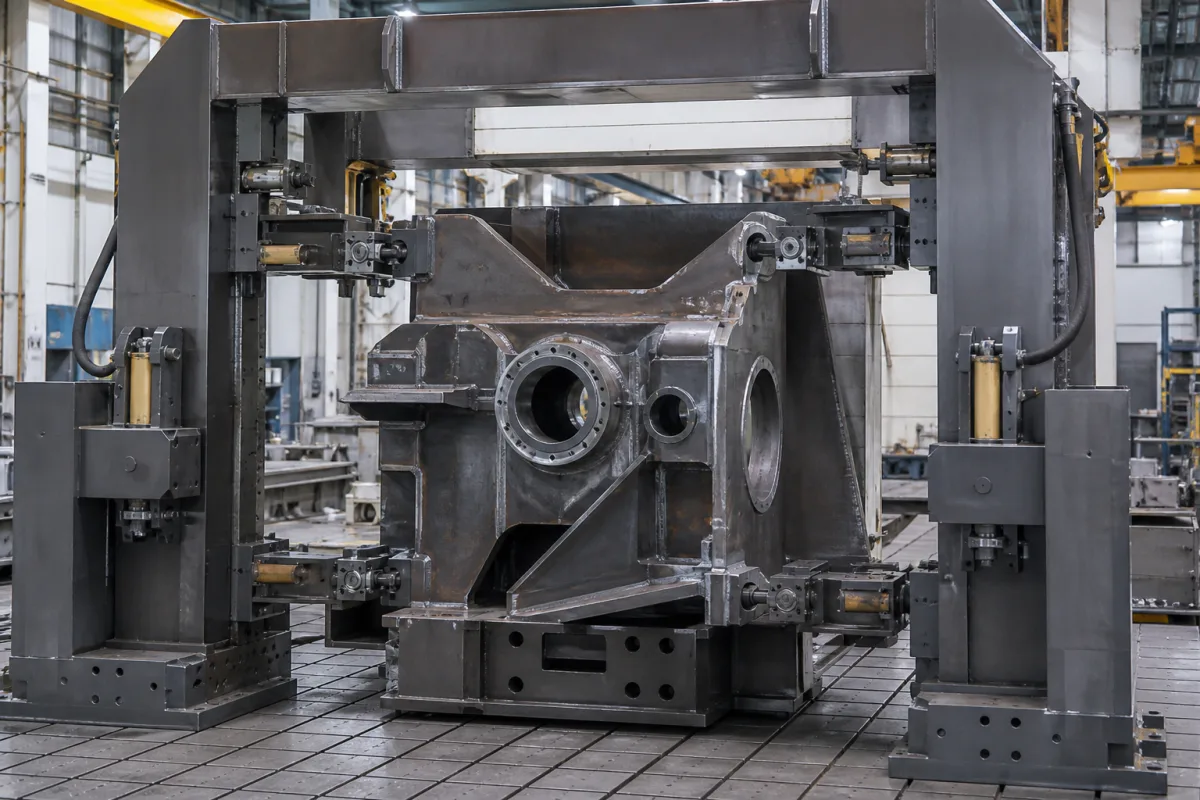
Hydraulic clamping frame for heavy weldments: block cylinders on a portal that hold a welded machine base in place
Portal frames with hydraulic block cylinders that hold a large weldment while it is welded or machined · 10 to 1,570 kN per cylinder at 500 bar, NBR seals to 100 °C or FKM to 200 °C, and why more clamps did not mean less distortion on a 10 m welded plate
Large welded structures such as machine bases are too heavy and too stiff to hold in a bench vice, and they move as weld heat goes in. A clamping frame surrounds the part with columns and a top beam, mounted on a floor plate, and presses it in place with hydraulic cylinders from the sides and from above. This page covers how much force those cylinders give, what the frame and its fixings must take back, how heat near the weld limits the seals, and what one published welding study found about the number of restraint points.
Hydraulic clamping frames and portal fixtures that hold large weldments and machine bases with block or push cylinders during welding, straightening or machining, mounted on floor or bed plates. Sheet-clamping frames of thermoforming and vacuum forming machines are covered with the machine on the Industrial vacuum forming machine page. Swing clamps, work supports and clamping sequence on machining fixtures for smaller parts are covered on the Hydraulic clamping system for machining fixtures page. Bench vices, toggle clamps for small parts, welding positioners and the floor plates themselves are outside this page.
CNFX editorial research · Sources checked October 13, 2026 · 3 sources
From 10 kN on a 16 mm piston to 1,570 kN on a 200 mm piston: push and pull force of 500 bar block cylinders
Römheld's data sheet B 1.5094 covers double-acting block cylinders in 11 sizes, piston diameters 16 to 200 mm and strokes 8 to 200 mm, for a maximum operating pressure of 500 bar. [1] Römheld states that double action generates force in both axial directions, push and pull, with exactly calculable and repeatable stroke times. [1]
Editorial calculation: push force is pressure times piston area. A 63 mm piston has an area of 31.2 cm², and at 500 bar (50 N/mm²) that gives 156 kN, matching the table. The pull figures are lower because the rod takes up part of the area on the return side: 93.0 kN on the 63 mm size is 60% of its push force.
AMF's block cylinder 63461 is single-acting with spring return: maximum operating pressure 500 bar, maximum clamping force 98 kN, stroke 20 mm and weight 5,670 g. [2] Editorial note: a spring-return cylinder retracts only with its spring force, so where a clamp has to pull free under load the double-acting type in the table above is the one to specify.
For each clamp point give the force needed, the direction (push down, push sideways), the stroke to clear the part when loading, and the supply pressure available; ask whether each cylinder is single- or double-acting.
02
Every kilonewton comes back into the frame: screws, side support and the crushing zone
A cylinder pushing on the part pushes equally on the column or beam it is bolted to, and both cylinder makers put the load path on the fixture builder. [1][2]
Editorial calculation: four 100 mm cylinders pushing down from a top beam at 500 bar put 4 × 392 kN = 1,568 kN, about 160 tonnes-force, into that beam and its columns; the beam must carry it with deflection small enough that the part is still held where intended. The figure is an illustration of scale, not a design load for a particular frame.
Requirement
Römheld block cylinders B 1.5094
AMF block cylinder 63461
Mounting screws
Screws of tensile strength 8.8 can in principle be used [1]
Danger of crushing in the effective area of the clamping bolt; the fixture maker must provide effective protection devices [1]
Single-acting types can suck in coolant on the return stroke; pipe the sintered breather to a clean, protected area [2]
Ask the frame supplier for the design clamp load per beam and column, the beam deflection at that load, the screw grade and the guarding around each cylinder.
03
NBR seals to 100 °C, FKM to 200 °C: cylinders working next to the weld
Römheld lists NBR seals and wipers for −25 to +100 °C and FKM for −15 to +200 °C, PTFE glide and back-up rings for −45 to +200 °C, and special versions to +250 °C on request; with FKM seals the cylinders are rated to operate up to 200 °C. [1] The housing is high-alloy steel, black oxide (larger sizes lacquered), and the piston rod case-hardened. [1]
Editorial note: on a clamping frame the cylinders nearest the joint see radiant heat and spatter; specify the seal material from the temperature measured at the cylinder, not from the room.
State the distance from each cylinder to the nearest weld, the welding process, preheat temperature if any, and whether spatter shields are wanted.
04
Three times fewer restraint points, 6–8% less distortion: what a 10 m welded steel plate study found
Mróz and co-authors (Rzeszów University of Technology, Naftoremont-Naftobudowa and the Łukasiewicz Centre of Welding) simulated and then welded a 10,000 mm storage tank bottom of 6 mm S235JR plate by MAG, with two layouts of wedge restraints. [3]
The aim was to tighten flatness from 0.25% × D = 25 mm, the tolerance met under EN 14015 by the previous technology, to 0.2% × D = 20 mm. The second fixture layout used three times fewer fixture points than the first; in the SYSWELD simulation the first layout's distortion was 6% higher before release from the fixtures and 8% higher after release. [3]
The authors caution that both layouts must be judged with the clamping force: with fewer clamps and less force the total may be too low, changing the restraint and the distortion. They also note that the stiffness and clamping method are hard to reproduce in a model and that small changes in clamping conditions can shift distortion substantially. [3] In the physical welding test with the second layout, Z-axis distortion ranged from −19 to +12 mm on one measurement line and −4 to +16 mm on the other, and the authors write that the 20 mm condition was met on the second line but not "for the majority of the points on line L1". [3]
Editorial note: this is a thin, wide plate, not a stiff machine base, so the percentages do not transfer; what does transfer is the method of comparing restraint layouts by simulation before the frame is built and measuring after release, not only while clamped.
Send the part drawing with weld sequence, the flatness or position tolerances after release, and ask the supplier how clamp positions and forces were chosen.
05
What to send for a hydraulic clamping frame
Paste it into your enquiry below or into an email to a maker, then replace every bracket.
Explore company information and manufacturing capabilities, then discuss the scope of your project with a relevant supplier.
Share this page
Compiled and source-reviewed by the CNFX editorial team.
Each manufacturer above links to the page on that company's own website where the product is listed, with the date we checked it. How we source and review
· Page last updated 13 October 2026
Buyer questions
How much force does a hydraulic block cylinder give at 500 bar?
Römheld's double-acting block cylinders push 10 kN with a 16 mm piston, 156 kN with 63 mm, 392 kN with 100 mm and 1,570 kN with 200 mm at 500 bar. [1]
Can clamping cylinders be used close to welding?
Römheld rates NBR seals to 100 °C and FKM seals to 200 °C, with special versions to 250 °C on request. [1]
What screws hold a block cylinder to the frame?
Römheld says 8.8 screws can in principle be used for its block cylinders; AMF requires class 12.9 for its 98 kN single-acting cylinder. [1][2]
Do more clamps reduce welding distortion?
In a 2026 study of a 10 m welded tank bottom, the layout with three times fewer restraint points gave 6–8% lower simulated distortion, but the authors stress that clamping force must stay sufficient. [3]
Sources and what still needs a direct check
Sources checked 2026-10-13. Cylinder sizes, forces, seals, mounting and safety notes come from Römheld data sheet B 1.5094; the single-acting cylinder from AMF's product page for block cylinder 63461; restraint layout and distortion from Mróz et al. in Materials (2026).