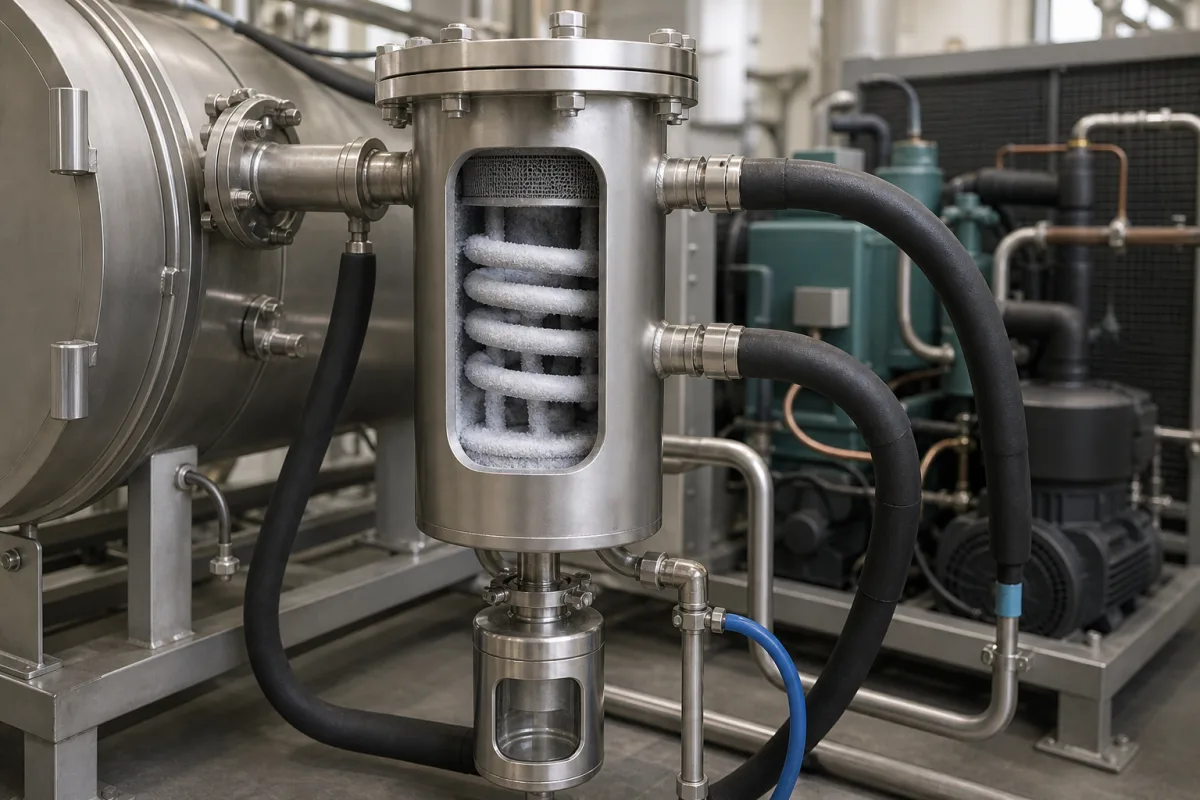
Vacuum cold traps and vapour condensers · Refrigerated or liquid-nitrogen-cooled traps placed between a vacuum chamber and its pump to condense solvents, water and corrosive vapours, chosen by trap temperature, collector capacity, solvent type and safe operation
A cold trap, or vapour condenser, is a chilled vessel in the vacuum line between a chamber and its pump. Vapours from the process freeze or condense on its cold surface instead of reaching and degrading the pump. Ask three things first: what vapours and how much must be collected, what trap temperature and cooling method (refrigeration or liquid nitrogen) they need, and how the trap will be drained, cleaned and operated safely.
Refrigerated and liquid-nitrogen cold traps and vapour condensers that protect vacuum pumps in laboratory and process vacuum systems. Process heat-exchanger condensers, freeze-dryer condensers as part of a dryer, cryopumps and vacuum pumps themselves are outside this page.
CNFX editorial research · Sources checked October 12, 2026 · 4 sources
Thermo Scientific describes its Savant refrigerated vapour traps as collecting solvents removed during vacuum evaporation, with vapours condensing in a collector so they do not reach and degrade the oil pump. The RVT450 cools from ambient to −50 °C for water and non-aggressive organic solvents; the RVT5105 cools to −105 °C for organic and highly volatile solvents such as methylene chloride, acetone, hexane and chloroform, acids, water and low- and high-boiling solvents. Both hold 4 L and use HCFC-free refrigeration. [1]
The RVT5105 uses two 1/3 hp compressors to reach −105 °C in under 40 minutes and has a 4 L stainless collector with a stainless drain port and nylon valve; it weighs 68 kg (150 lb) and measures 61 × 61 × 47 cm, against 32 kg for the RVT450. Both come in 115 V/60 Hz and 230 V/50 Hz versions. [1]
Weizmann Institute safety guidance says a cold trap safeguards vacuum lines and pumps by condensing solvents and volatile liquids and recommends one to keep a vacuum pump working at lower pressures; it describes traps cooled by placing them in a dewar of liquid nitrogen. [2]
DigiVac's 4-inch liquid-nitrogen cold trap uses a "cold thimble" design: the thimble holds liquid nitrogen, which DigiVac gives as −187 °C, and its outer surface, exposed to the vacuum system, condenses molecules in the vapour phase. DigiVac lists a water-vapour pumping speed at the trapping surface of 95 L/s per square inch and a "theoretical" water-vapour pressure at the thimble of 10⁻²¹ Torr. The trap is electropolished 304 stainless steel with an easily removable thimble and comes with an NW16 or NW25 port. [4]
Give the supplier the vapours and their amounts per run, the lowest temperature needed to condense them, vacuum level and pump size, cooling method (refrigerated or liquid nitrogen), collector capacity and drain arrangement, materials for corrosive vapours, electrical supply, and installation (bench, inline, skid).
02
Operate, drain and clean the trap safely
For liquid-nitrogen traps, the Weizmann guidance warns that liquid oxygen (blue) can form in nitrogen-cooled vessels and may cause a serious explosion, so the trap must always be removed from the liquid nitrogen before the vacuum is turned off. It also says to close the valve between vessel and pump before stopping the pump and to release the vacuum immediately after shutdown to avoid sucking pump oil into the system. [2]
The guidance says to let the trap warm to room temperature before disposing of collected solvents, to leave traps that may hold toxic or corrosive condensate in a fume hood overnight before washing, and to wear safety glasses, lab coat, closed shoes and gloves, plus a full face shield and cryogenic gloves for liquid nitrogen. [2]
Editorial calculation: the RVT5105's −105 °C is 55 K colder than the RVT450's −50 °C. [1]
03
Compare trap temperature grades and pull-down time
Labconco's CentriVap cold trap product page lists three collector temperature grades sharing a 4-litre stainless steel collector, a stainless steel drain port with polypropylene valve, a lid with two quick-disconnect fittings for 1/2 in ID hose, and an HCFC/CFC-free refrigeration system. A temperature graph lights green when the collector coil reaches its operating temperature. [3]
The page links a boiling point calculator for choosing the grade against the solvent, and the colder grades use two compressors. Compare collector volume, the lowest temperature and the pull-down time with the vapour load of your evaporator or vacuum process, alongside the safe-operation points above for liquid-nitrogen traps. [3][2]
Editorial calculation: the −105 °C grade is 55 °C colder than the −50 °C grade but more than doubles the unit weight (68 kg against 32 kg).
Labconco CentriVap grade
Compressors
Pull-down
Operating-temperature indicator
Dimensions (w × d × h)
Weight
−50 °C
One 1/3 hp
To −50 °C in under 30 min
−40 °C
14.5 × 24.2 × 13.8 in
32 kg
−84 °C
Two 1/3 hp
To −84 °C in under 40 min
−65 °C
14.5 × 22.0 × 20.9 in
61 kg
−105 °C
Two 1/3 hp
To −105 °C in under 40 min
−65 °C
24.1 × 23.9 × 17.6 in
68 kg
State the solvents and their freezing points, vapour load per run, required trap temperature and collector volume, and ask for pull-down time, drain arrangement and hose connection size.
04
Pull-down, condensing capacity and drain method: what to ask before buying
Ask any supplier for lowest trap temperature and pull-down time, condensing capacity and collector volume, compatible solvents and acids, wetted materials, pump size it suits, refrigerant, power supply, drain and defrost method, dimensions and weight.
05
Collector, LN2 thimble, refrigeration and the shutdown valve
Two cooling routes share this list: a refrigerated collector or a liquid-nitrogen thimble. The isolation valve row matters for the shutdown order the Weizmann guidance sets out. [4][2]
Refrigeration, temperature, supply and material values found so far
Surface area, coolant flow, accuracy, pressure drop, power draw and IP rating have no published figure in the sources reviewed; the lowest temperature and pull-down rows are the ones that decide which grade condenses your solvent. [3]
Explore company information and manufacturing capabilities, then discuss the scope of your project with a relevant supplier.
Share this page
Compiled and source-reviewed by the CNFX editorial team.
Each manufacturer above links to the page on that company's own website where the product is listed, with the date we checked it. How we source and review
· Page last updated 13 October 2026
Buyer questions
Why fit a cold trap before a vacuum pump?
It condenses solvent vapours so they do not reach and degrade the pump. [1][2]
How cold do refrigerated cold traps get?
Thermo Scientific lists −50 °C (RVT450) and −105 °C (RVT5105). [1]
What is the main hazard with liquid-nitrogen traps?
Liquid oxygen can condense and explode; remove the trap from the nitrogen before switching off the vacuum. [2]
How cold can a refrigerated cold trap get?
Labconco's CentriVap traps come in −50 °C, −84 °C and −105 °C grades; the two colder grades use two 1/3 hp compressors and reach temperature in under 40 minutes. [3]
How fast does a liquid-nitrogen cold trap pump water vapour?
DigiVac gives 95 L/s per square inch of trapping surface for water vapour on its 4-inch LN2 cold-thimble trap. [4]
Sources and what still needs a direct check
Sources checked 2026-10-12. Thermo Fisher Scientific and Labconco make refrigerated vapour traps; DigiVac makes a liquid-nitrogen cold-thimble trap; the Weizmann Institute publishes vacuum safety guidance.