Editorial Technical Reference

Component Sensor

This page explains how Component Sensor is classified within Machinery and Equipment Manufacturing. Technical values and manufacturer relationships are research references; confirm the current specification and supplier evidence for each order.

Technical Definition & Core Assembly

A sensor that detects the presence, position, or characteristics of components within an automated feeding system.
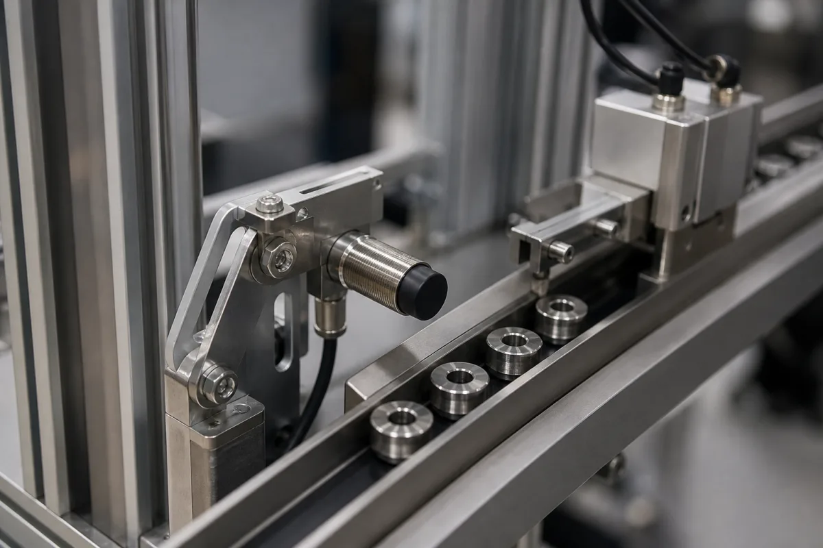
Representative product image. Confirm appearance and specifications with the manufacturer.

Product Specifications

Technical details and manufacturing context for Component Sensor

Definition
The Component Sensor is a specialized sensing device designed for integration into automated component feeders. Its primary function is to monitor and verify the presence, orientation, position, or specific attributes (such as size or type) of components as they are fed, sorted, or positioned for subsequent assembly or processing operations. By ensuring that the correct component is in the correct place at the correct time, this sensor enables precise automation and helps prevent errors in production lines.

Typical applications include verifying that a component has been correctly picked up by a feeder, confirming orientation before assembly, or detecting jams or misalignments. The sensor operates by emitting a signal—such as an optical light beam, ultrasonic waves, or a magnetic field—and detecting changes in the received signal caused by the presence or passage of a component. Common types include photoelectric sensors (through-beam, retro-reflective, diffuse), proximity sensors (inductive, capacitive), and vision sensors.

Key parameters to consider when selecting a component sensor include detection range (typically 5–50 mm for inductive types, with larger ranges available for optical types), supply voltage (10–30 V DC, reverse polarity protected, 24 V DC nominal), maximum output current (≤200 mA), switching frequency (100–1000 Hz, depending on sensing distance and output type), repeat accuracy (±0.05 mm at constant temperature and supply voltage), operating temperature (-25 to 70 °C), protection class (IP67, dust-tight and protected against immersion), housing material (stainless steel 304, corrosion-resistant), connection type (M12 quick disconnect, cable versions available), and weight (30–50 g, depending on housing length and connection).

These values are typical reference ranges and must be verified for the specific model and application. The sensor is constructed with a plastic housing, a stainless steel sensing face, and electronic components including a PCB, LED/phototransistor, and ICs. It is designed for industrial environments and meets the IP67 protection standard. Always confirm model-specific values and standards with the legal manufacturer or supplier before procurement.
Working Principle
The sensor emits a signal, such as an optical beam, ultrasonic wave, or magnetic field, and detects changes in that signal when a component enters its sensing field. For photoelectric types, the component interrupts or reflects light; for inductive types, it alters the electromagnetic field; for capacitive types, it changes capacitance. The sensor's output switches state when the detected change exceeds a threshold, providing a digital signal to the control system. This allows the system to confirm the presence, position, or characteristics of the component.
Common Materials
Plastic Housing, Stainless Steel Sensing Face, Electronic Components (PCB, LED/Phototransistor, ICs)
Technical Parameters
ParameterTypical rangeNotes & selection driver
Detection Range5–50 mmTypical for inductive sensors; larger ranges available for optical types.
Supply Voltage10–30 V DCReverse polarity protected; 24 V DC nominal.
Output Current≤200 mAMaximum continuous output current.
Switching Frequency100–1000 HzDepends on sensing distance and output type.
Repeat Accuracy±0.05 mmAt constant temperature and supply voltage.
Operating Temperature-25–70 °CExtended range available on request.
Protection ClassIP67Dust-tight and protected against immersion.IEC 60529
Housing Material304 Stainless steelCorrosion-resistant for industrial environments.ASTM A276
Connection TypeM12 connectorQuick disconnect; cable versions available.IEC 61076-2-101
Weight30–50 gDepends on housing length and connection.

Ranges are indicative industry figures for RFQ preparation, not a supplier commitment. Confirm every value and standard with the legal manufacturer before ordering.

Components / BOM
  • Emitter Part
    Generates the sensing signal (e.g., light, ultrasonic pulse, magnetic field).
    Material: LED/Laser Diode (optical), Piezoelectric Crystal (ultrasonic), Coil (inductive)
  • Receiver/Detector
    Detects the signal after interaction with the target component and converts it to an electrical signal.
    Material: Phototransistor/Photodiode (optical), Piezoelectric Crystal (ultrasonic), Circuitry (inductive)
  • Housing Part
    Provides mechanical protection, mounting points, and environmental sealing for internal electronics.
    Material: Plastic (e.g., PBT), Stainless Steel, Aluminum
  • Signal Processing Circuitry
    Amplifies, filters, and processes the detector signal to generate a clean, reliable output signal.
    Material: Printed Circuit Board (PCB), Integrated Circuits (ICs), Resistors, Capacitors

Applied To / Applications

This component is essential for the following industrial systems and equipment:

Industrial Ecosystem & Supply Chain Structure

Complementary Systems
Downstream Applications
Specialized Tooling

Application Fit & Sizing Matrix

Operational Limits
pressure: 0 to 10 bar
other spec: Max flow rate: 5 m/s, Max slurry concentration: 15% solids by weight
temperature: -20°C to +85°C
Media Compatibility
✓ Plastic pellets ✓ Metal components ✓ Food-grade powders
Unsuitable: Corrosive chemical environments (e.g., strong acids, chlorides)
Sizing Data Required
  • Component size range (min/max dimensions)
  • Required detection distance
  • System feed rate (components per minute)

Reliability & Engineering Risk Analysis

Failure Mode & Root Cause
Signal drift/calibration loss
Cause: Thermal cycling, component aging, or contamination of sensing elements leading to inaccurate readings
Electrical connection failure
Cause: Vibration-induced wire fatigue, corrosion at terminals, or moisture ingress causing short circuits or open circuits
Maintenance Indicators
  • Erratic or inconsistent readings compared to process expectations
  • Complete loss of signal output or communication failure with control system
Engineering Tips
  • Implement regular calibration schedules using traceable standards and document drift trends for predictive replacement
  • Use vibration-resistant connectors, proper cable strain relief, and environmental sealing appropriate for the installation conditions

Indicative industry ranges for design and RFQ preparation. Confirm the exact figures and applicable standard with the manufacturer before specifying.

Compliance & Manufacturing Standards

Applicable Standards
IEC 60529:2013 - Degrees of protection provided by enclosures (IP Code) CE Marking - Compliance with EU directives (e.g., EMC Directive 2014/30/EU)

Quoted from the published standard.

Manufacturing Precision
  • Dimensional accuracy: +/-0.05mm for critical features
  • Electrical output stability: +/-1% of nominal value across operating range
Quality Inspection
  • Environmental testing (temperature, humidity, vibration per IEC 60068 series)
  • Calibration verification against traceable reference standards

Manufacturers of Component Sensor

Manufacturer profiles associated with Component Sensor.

Sourcing Component Sensor from China?
Tell us your specification and target quantity — we will match it against manufacturer records and come back with the factories that fit.
Request manufacturers We manufacture this

Manufacturer listings support early research and capability understanding. They are not certification, ranking, or transaction guarantees.

Technical documentation
Request current drawings, revision history, and a signed specification sheet.
Manufacturing capability
Verify equipment lists, process limits, capacity, and representative production evidence.
Inspection readiness
Confirm test methods, calibrated equipment, sampling plans, and traceable reports.
Supplier transparency
Check the legal entity, factory address, ownership, certifications, and direct contacts.

CNFX does not score or rank suppliers. Buyers must verify all claims and documents with the legal manufacturer before ordering.

Supply Chain Compatible Machinery & Devices

Hydraulic Press

Industrial machine using hydraulic pressure to compress, form, or assemble materials

Explore Specs →
Heavy-Duty CNC Plasma Cutting Machine

The Heavy-Duty CNC Plasma Cutting Machine is a standalone industrial device designed for cutting conductive metals such as steel, stainless steel, aluminum, and copper alloys.

Explore Specs →
Automated Powder Coating System

Integrated industrial system for applying dry powder coatings to metal substrates.

Explore Specs →
Centrifugal Pump Impeller

The centrifugal pump impeller is a critical rotating component that converts mechanical energy from the motor into kinetic energy in fluid systems.

Explore Specs →

Frequently Asked Questions

What is the typical detection range of this component sensor?

The typical detection range is 5–50 mm for inductive sensors, with larger ranges available for optical types. However, the exact range depends on the specific model and sensing technology. Always verify the detection range for your intended application with the manufacturer.

What supply voltage does the sensor require?

The sensor operates on a supply voltage of 10–30 V DC, with a nominal voltage of 24 V DC. It is reverse polarity protected. Ensure your power supply meets these requirements and confirm the exact voltage range for the specific model.

What is the protection class of the sensor?

The sensor has a protection class of IP67, meaning it is dust-tight and protected against immersion in water. This makes it suitable for industrial environments. However, verify the IP rating for the specific model, as it may vary.

What connection type is available?

The sensor features an M12 quick-disconnect connector, with cable versions available on request. The M12 connector is standard per IEC 61076-2-101. Confirm the connection type and cable length with the supplier for your application.

Data Basis

Editorial classification, named public sources where available, and source-reviewed manufacturer records.

Preliminary Technical Classification
This page supports structured research, RFQ preparation, and supplier evaluation. It does not replace buyer-led supplier qualification, standards review, or technical approval.
Buyer enquiry

Request manufacturing insight for Component Sensor

Ask for use case, specification boundaries, supplier type, and RFQ preparation information for this product.

Where it goes
Straight to the CNFX editorial desk, and to the manufacturer if this product is linked to a claimed profile. Nothing is broadcast to a supplier list.
Your details stay here
We do not sell or rent enquiry data, and we do not add you to a mailing list. Used only to answer this request.
No commission, no middleman
CNFX is a directory. We take no cut of any order and never negotiate on a supplier's behalf.
What we don't claim
A listing is not an endorsement. Qualify every supplier and verify every figure yourself before ordering.

Your business information is used only to process this request.

Thank you! Your message has been sent. We'll respond within 1–3 business days.
Sorry, we couldn't send your message. Please try again, or email us at contact@cnfx.com.

Need to Manufacture Component Sensor?

Compare manufacturer profiles with relevant product and process capability.

Previous Product
Compliance Checker
Next Product
Compressed Air System
Get QuotesChat