Editorial Technical Reference

Contact Block

This page explains how Contact Block is classified within Machinery and Equipment Manufacturing. Technical values and manufacturer relationships are research references; confirm the current specification and supplier evidence for each order.

Technical Definition & Core Assembly

A modular electrical switching component that houses and operates the contacts within an emergency stop button assembly.
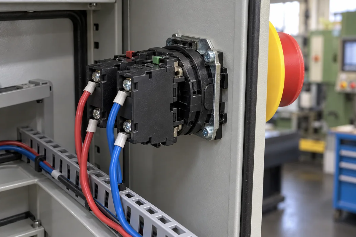
Representative product image. Confirm appearance and specifications with the manufacturer.

Product Specifications

Technical details and manufacturing context for Contact Block

Definition
The contact block is a critical sub-component of an emergency stop button system that contains the electrical contacts and switching mechanism. When the emergency stop button is activated, the contact block mechanically opens or closes the electrical circuit to immediately cut power to machinery or equipment, ensuring safety shutdown. This directory entry covers a generic contact block intended for use in emergency stop circuits, typically mounted behind the actuator in a control panel or enclosure. The block is constructed with a thermoset plastic housing, silver alloy contacts (AgNi10), and copper terminals. It is designed for screw clamping of conductors from 1×0.5 to 2.5 mm². Key electrical parameters include a rated insulation voltage of 690 V, a rated operational voltage of 24–600 V AC/DC, and a rated operational current of 10 A (AC-15). Contact resistance is ≤50 mΩ initially. Mechanical endurance is 1,000,000 operations, and electrical endurance is 100,000 operations at rated current and voltage. The ambient operating temperature range is -25 to 70 °C, with storage from -40 to 85 °C. The degree of protection ranges from IP20 to IP65, depending on the enclosure and mounting. Weight is approximately 30–50 g per block. These values are reference ranges based on typical designs and must be verified for the specific model and application. The contact block operates through mechanical actuation from the emergency stop button's plunger or actuator. When the emergency stop is pressed, the actuator moves within the contact block, causing the internal contacts to change state (typically from normally closed to open), breaking the electrical circuit and stopping the connected equipment. This product is a component; selection requires confirming compatibility with the emergency stop actuator, electrical ratings, and environmental conditions. Always verify model-specific values and standards with the legal manufacturer or supplier before installation.
Working Principle
The contact block operates through mechanical actuation from the emergency stop button's plunger or actuator. When the emergency stop is pressed, the actuator moves within the contact block, causing the internal contacts to change state (typically from normally closed to open), breaking the electrical circuit and stopping the connected equipment. The switching mechanism is designed to provide a positive break, ensuring reliable circuit interruption. The contact block is typically wired in series with the control circuit of the machinery. Upon actuation, the normally closed contacts open, de-energizing the load. The block may also include normally open contacts for signaling purposes. The mechanical linkage ensures that the contacts remain in the actuated state until the button is manually reset. The design must meet the requirements of IEC 60947-5-1 for emergency stop devices, including mechanical and electrical endurance. The contact material, silver alloy AgNi10, provides low contact resistance and resistance to welding. The thermoset plastic housing provides electrical insulation and mechanical strength. The copper terminals ensure reliable electrical connections. The operating principle is straightforward: mechanical input from the actuator translates into a change in contact state, thereby controlling the electrical circuit.
Common Materials
Thermoset Plastic, Silver Alloy Contacts, Copper Terminals
Technical Parameters
ParameterTypical rangeNotes & selection driver
Rated Insulation Voltage690 VMaximum voltage for insulation designIEC 60947-5-1
Rated Operational Voltage24–600 V AC/DCAC and DC applicationsIEC 60947-5-1
Rated Operational Current10 AAC-15 utilization categoryIEC 60947-5-1
Contact Resistance≤50 Initial value, new contact
Mechanical Endurance1,000,000 operationsNo load operationsIEC 60947-5-1
Electrical Endurance100,000 operationsAt rated current and voltageIEC 60947-5-1
Ambient Operating Temperature-25–70 °CStorage temperature -40–85°CIEC 60947-5-1
Degree of ProtectionIP20–IP65Depends on enclosure and mountingIEC 60529
Contact MaterialAgNi10Silver alloy for low resistance
Terminal TypeScrewClamping range 1×0.5–2.5 mm²
Weight30–50 gSingle block, without mounting base

Ranges are indicative industry figures for RFQ preparation, not a supplier commitment. Confirm every value and standard with the legal manufacturer before ordering.

Components / BOM
  • Contact Set Part
    Electrical switching elements that make or break the circuit
    Material: Silver Alloy
  • Actuator Interface
    Mechanical interface that receives motion from the emergency stop button
    Material: Thermoset Plastic
  • Terminal Block
    Connection points for wiring to the control circuit
    Material: Copper Alloy
  • Housing Part
    Protective enclosure for internal components
    Material: Thermoset Plastic

Applied To / Applications

This component is essential for the following industrial systems and equipment:

Industrial Ecosystem & Supply Chain Structure

Complementary Systems
Downstream Applications
Specialized Tooling

Application Fit & Sizing Matrix

Operational Limits
current: Up to 10A
voltage: Up to 600V AC/DC
temperature: -20°C to +85°C
electrical life: 100,000 operations at rated load
mechanical life: 1,000,000 operations minimum
dielectric strength: 2,500V AC for 1 minute
insulation resistance: ≥100 MΩ at 500V DC
Media Compatibility
✓ Industrial control panels ✓ Machinery safety circuits ✓ Dry, clean electrical environments
Unsuitable: Wet, corrosive, or explosive atmospheres without proper IP-rated enclosures
Sizing Data Required
  • Rated voltage and current of the controlled circuit
  • Number of normally open/normally closed contacts required
  • Mounting configuration and panel cutout dimensions

Reliability & Engineering Risk Analysis

Failure Mode & Root Cause
Wear and tear of contact surfaces
Cause: Repeated mechanical engagement/disengagement leading to material degradation and loss of electrical conductivity
Corrosion and oxidation
Cause: Exposure to moisture, chemicals, or atmospheric contaminants causing surface deterioration and increased resistance
Maintenance Indicators
  • Visible arcing, sparking, or discoloration at contact points during operation
  • Audible buzzing, crackling, or intermittent connection sounds indicating poor contact
Engineering Tips
  • Implement regular contact resistance testing and cleaning schedule using appropriate contact cleaners and non-abrasive tools
  • Apply protective coatings or use corrosion-inhibiting compounds on contact surfaces in harsh environments

Indicative industry ranges for design and RFQ preparation. Confirm the exact figures and applicable standard with the manufacturer before specifying.

Compliance & Manufacturing Standards

Applicable Standards
ANSI/ASME B46.1-2019 Surface Texture

Quoted from the published standard.

Manufacturing Precision
  • Bore Diameter: +/-0.02mm
  • Surface Flatness: 0.1mm
Quality Inspection
  • Dimensional Verification with CMM
  • Hardness Testing (Rockwell C Scale)

Manufacturers of Contact Block

1 company lists this product among what they make. Company figures are quoted from each company's own website; every card states where the relationship came from.

Bühler Group
Hong Kong, CN
Listed on the company's own website · profile compiled by CNFX from public sources

Manufacturer listings support early research and capability understanding. They are not certification, ranking, or transaction guarantees.

Technical documentation
Request current drawings, revision history, and a signed specification sheet.
Manufacturing capability
Verify equipment lists, process limits, capacity, and representative production evidence.
Inspection readiness
Confirm test methods, calibrated equipment, sampling plans, and traceable reports.
Supplier transparency
Check the legal entity, factory address, ownership, certifications, and direct contacts.

CNFX does not score or rank suppliers. Buyers must verify all claims and documents with the legal manufacturer before ordering.

Supply Chain Compatible Machinery & Devices

Hydraulic Press

Industrial machine using hydraulic pressure to compress, form, or assemble materials

Explore Specs →
Heavy-Duty CNC Plasma Cutting Machine

The Heavy-Duty CNC Plasma Cutting Machine is a standalone industrial device designed for cutting conductive metals such as steel, stainless steel, aluminum, and copper alloys.

Explore Specs →
Automated Powder Coating System

Integrated industrial system for applying dry powder coatings to metal substrates.

Explore Specs →
Centrifugal Pump Impeller

The centrifugal pump impeller is a critical rotating component that converts mechanical energy from the motor into kinetic energy in fluid systems.

Explore Specs →

Frequently Asked Questions

What is the rated insulation voltage of this contact block?

The rated insulation voltage is 690 V, as per IEC 60947-5-1. This is the maximum voltage for insulation design. Always verify the specific model's rating with the manufacturer.

What is the mechanical endurance of the contact block?

The mechanical endurance is 1,000,000 operations without load, according to IEC 60947-5-1. This indicates the expected lifespan under mechanical actuation. Actual life may vary with operating conditions.

What is the degree of protection for this contact block?

The degree of protection ranges from IP20 to IP65, depending on the enclosure and mounting. IP20 is for basic protection, while IP65 offers dust-tight and water-jet protection. Confirm the final rating with the enclosure used.

What is the contact material used?

The contact material is silver alloy AgNi10, which provides low contact resistance and good resistance to welding. This is a common material for switching contacts in control circuits.

Data Basis

Editorial classification, named public sources where available, and source-reviewed manufacturer records.

Preliminary Technical Classification
This page supports structured research, RFQ preparation, and supplier evaluation. It does not replace buyer-led supplier qualification, standards review, or technical approval.
Buyer enquiry

Request manufacturing insight for Contact Block

Ask for use case, specification boundaries, supplier type, and RFQ preparation information for this product.

Where it goes
Straight to the CNFX editorial desk, and to the manufacturer if this product is linked to a claimed profile. Nothing is broadcast to a supplier list.
Your details stay here
We do not sell or rent enquiry data, and we do not add you to a mailing list. Used only to answer this request.
No commission, no middleman
CNFX is a directory. We take no cut of any order and never negotiate on a supplier's behalf.
What we don't claim
A listing is not an endorsement. Qualify every supplier and verify every figure yourself before ordering.

Your business information is used only to process this request.

Thank you! Your message has been sent. We'll respond within 1–3 business days.
Sorry, we couldn't send your message. Please try again, or email us at contact@cnfx.com.

Need to Manufacture Contact Block?

Compare manufacturer profiles with relevant product and process capability.

Previous Product
Z-axis Ram/Spindle
Last Product
Get QuotesChat