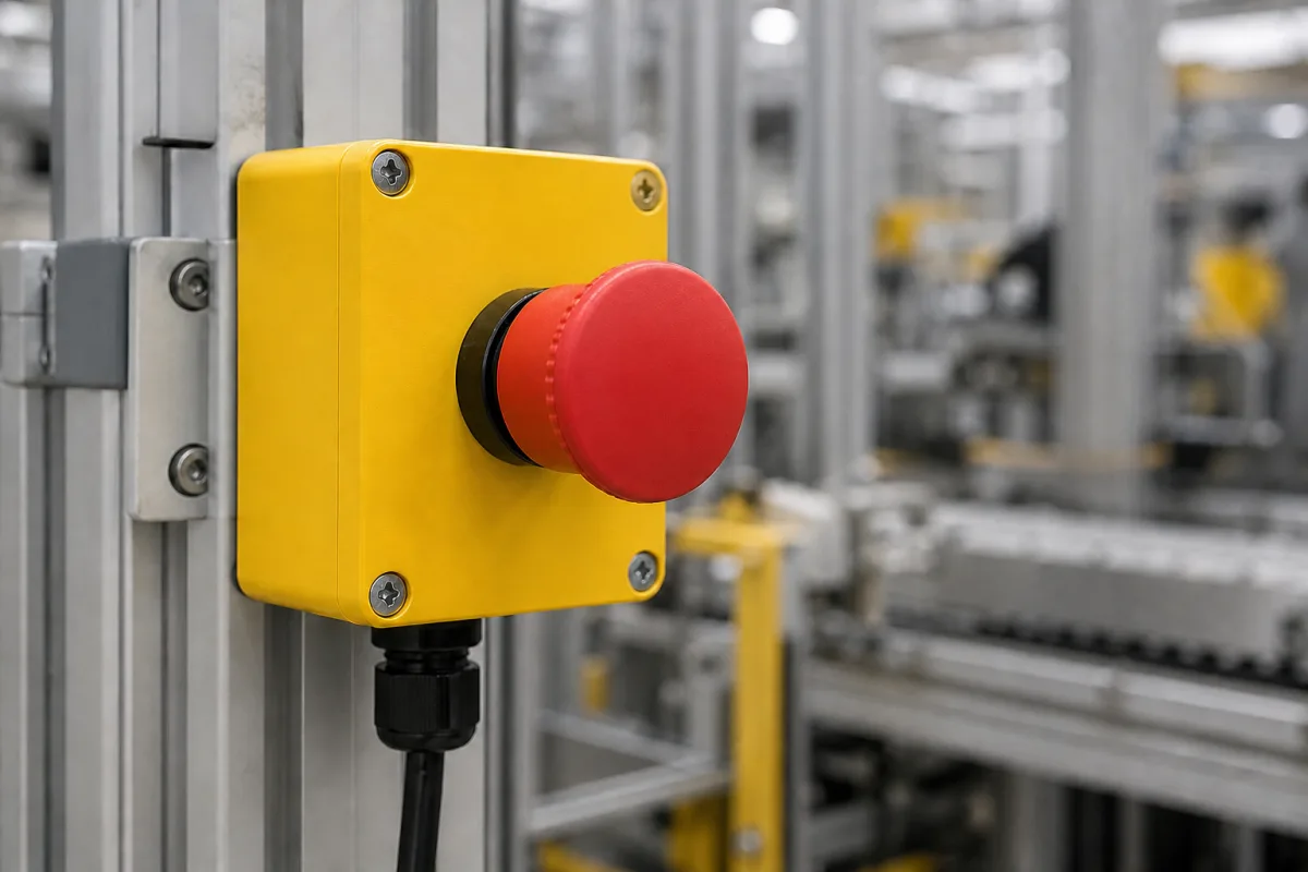
Machine emergency stop devices · red-on-yellow mushroom actuators, mechanical latching, direct (positive) opening contacts, ratings and durability
An emergency stop button is a red mushroom-head push-button on a yellow background or yellow enclosure, that an operator strikes to stop a machine in an emergency; it latches in the pressed position and must be deliberately reset by turning or pulling, and its normally closed contacts are forced open mechanically. Ask three things first: whether the device is built and tested to the emergency stop standards for your market, whether its contacts have direct (positive) opening action, and what electrical ratings, protection and durability it has for your control circuit and environment.
Emergency stop push-buttons with mechanical latching (panel-mounted 22 mm devices and enclosed control stations) for machinery control circuits. Ordinary stop buttons, pull-cord switches, supply disconnect switches used as emergency stops, safety relays and wireless emergency stops are outside this page except where compared.
CNFX editorial research · Sources checked October 12, 2026 · 5 sources
A note approved by the EU Machinery Working Group (MD WG 2010-03 rev. 2, 2014) explains that Annex I 1.2.4.3 of the Machinery Directive 2006/42/EC requires machinery, with stated exceptions, to have one or more emergency stop devices with clearly identifiable, clearly visible and quickly accessible controls, because a split-second reaction may be crucial. It cites EN ISO 13850 for the emergency stop function and the red push-button against a yellow background, and EN 60947-5-5 for electrical emergency stop devices with mechanical latching. [1]
Where electrical switches are used, the note says they should have direct opening action in accordance with EN 60947-5-1 Annex K. Protective collars must not impair accessibility, and a full collar is in principle not acceptable unless its suitability is shown by testing; a flap-stop device that can be left open cannot provide the emergency stop function. Light curtains, mats and laser scanners are protective devices, not emergency stop devices, and a supply disconnecting device may serve as an emergency stop only in limited cases, coloured red on a yellow background. [1]
Editorial note: placement and number of devices depend on the machine's risk assessment, which the note does not cover; ask the machine builder, not only the button supplier, for that.
Give the supplier the machine and market (CE, UL/CSA), mounting (22 mm panel hole or enclosed station), number of NC and NO contacts, control voltage and current, reset type (turn or pull), environment (IP, washdown, outdoor, low temperature), illumination needs, enclosure material and cable entry, and required certificates.
02
Check electrical ratings, protection and durability
Schneider Electric's data sheet for its XB4BS8442 emergency stop push-button (red 40 mm mushroom, 22 mm mounting, trigger action with mechanical latching, turn to release, 1 NC) lists positive opening conforming to IEC 60947-5-1 Annex K, 1.5 mm travel to change the NC contact state and 4.3 mm total travel, a rated insulation voltage of 600 V, a rated impulse withstand voltage of 6 kV, and a conventional thermal current of 10 A. [2]
It gives rated operational currents of 3 A at 240 V AC-15 and 0.27 A at 250 V DC-13, mechanical durability of 300,000 cycles and electrical durability of 1,000,000 cycles at AC-15 2 A 230 V, operating temperature of −40 to +70 °C, IP66, IP67, IP69 and IP69K, and lists ISO 13850 and IEC 60947-5-5 among its standards. [2]
Editorial calculation: if an emergency stop is pressed and reset 20 times a day for tests and stops, 300,000 mechanical cycles last 300,000 / (20 × 365) ≈ 41 years; at 200 times a day, about 4 years. Usage rates are assumed examples; check durability figures on the device you buy.
03
Compare a second maker's data sheet line by line
Eaton's data sheet for the M22-PV (Moeller RMQ-Titan series) describes a red, 38 mm mushroom-head emergency stop pushbutton on a yellow base with pull-to-release unlatching, tamper-proof according to ISO 13850 and EN 418, for a 22.5 mm mounting hole, with up to four M22 contact elements. [3]
Set these figures beside the Schneider XB4BS8442 data above: release method (turn or pull), actuator diameter, contact configuration, mechanical durability and enclosure protection all differ between makers' devices, so state the ones your machine needs. [3][2]
Editorial calculation: at the 600 operations per hour rating, 100,000 operations would last about 167 hours of continuous cycling; in emergency use the device sees far fewer operations, but routine function tests count toward the total.
M22-PV data (Eaton)
Value
Actuator diameter / colour
38 mm, red RAL 3000 on yellow base
Unlocking
Pull-to-release
Actuating force
50 N
Mechanical lifespan
100,000 operations
Operating frequency
600 operations/h
Degree of protection
IP66, NEMA 4X and 13
Ambient temperature
−25 to +70 °C
Shock resistance
50 g, 11 ms sinusoidal, IEC/EN 60068-2-27
Standards listed
IEC/EN 60947-5, UL 508, CSA C22.2 No. 14-05 and 94-91
State the release method, actuator size, number of NC contacts, protection rating and ambient range, and ask for mechanical lifespan, actuating force and the standards the device is certified to.
04
Read a Chinese maker's emergency stop data: ONPOW HBY5 and ONPOW26
ONPOW, a Chinese push-button maker, publishes an emergency stop range by panel cut-out and rating. Its 16 mm and 19 mm LAS1 series are rated Ui 250 V and Ith 5 A, the 22 mm LAS0 series Ui 500 V and Ith 10 A, and the 22 mm HBY5, Y090 and ONPOW26 series Ui 660 V and Ith 10 A. ONPOW states the ONPOW26 series conforms to GB/T 14048.5 Annex K and takes 1 to 4 slow-action contact blocks. [5]
The HBY5 data sheet lists IEC 60947-5-1 and GB 14048.5, a 22 mm mounting hole, slow-break self-cleaning silver-alloy contacts, 1 to 8 stackable switch units and a push-pull emergency stop variant (code MT) beside the turn-to-release type (TS). Its durability lines differ by actuator: at least 1 million operations for momentary buttons, 500,000 for latching and selector knobs, but 200,000 for key knobs and emergency stop buttons, with electrical life of at least 50,000 operations. [4]
Editorial note: the HBY5 rates its emergency stop at −25 to +55 °C, against −40 to +70 °C for the Schneider XB4BS8442 and −25 to +70 °C for the Eaton M22-PV, so check the upper temperature limit for cabinets in hot plants. [4][2][3]
Suppliers linked to this page list emergency stop buttons; each card links to the page reviewed.
Listings include metal and plastic emergency stop switches among push-button and indicator ranges, 22 mm metal and LED-illuminated emergency stop buttons, and emergency stop buttons alongside tower lights and indicators. Ask each for compliance with ISO 13850 and IEC 60947-5-5, direct-opening contacts and test reports.
06
Trace the device components
This is a functional reference built from the sources cited; it is not one maker's specification.
Prevents accidental operation; must not impair access. [1]
Collar type.
07
Fill the specification fields with values for your control circuit
An emergency stop button quotation needs values for your control circuit. The table explains each field, gives published values where a reviewed source states them, and says what to obtain from the supplier.
Field
What it means and published values
Ask the supplier for
Rated Operating Voltage (V AC/DC)
Example: 3 A at 240 V AC-15; 0.27 A at 250 V DC-13. [2]
Explore company information and manufacturing capabilities, then discuss the scope of your project with a relevant supplier.
Share this page
Compiled and source-reviewed by the CNFX editorial team.
Published product pages show what a company offers, not tested performance or certification. Confirm the legal seller, factory, certificates and scope for your order. How we source and review
· Page last updated 13 October 2026
Buyer questions
Why are emergency stop buttons red on yellow?
The EU Machinery Working Group note cites EN ISO 13850 for a red push-button against a yellow background so the device is clearly identifiable. [1]
What is direct opening action?
The note says electrical emergency stop switches should have direct opening action to EN 60947-5-1 Annex K; Schneider lists positive opening to that annex for its XB4 device. [1][2]
Is a light curtain an emergency stop?
No; the note says light curtains, mats and laser scanners are protective devices, not emergency stop devices. [1]
How many operations is an emergency stop button rated for?
Eaton's M22-PV data sheet lists a mechanical lifespan of 100,000 operations at up to 600 operations per hour, with a 50 N actuating force. [3]
Do emergency stop buttons have a lower mechanical life than ordinary push-buttons?
In ONPOW's HBY5 data sheet, yes: at least 200,000 operations for emergency stop buttons against at least 1 million for momentary buttons. [4]
Sources and what still needs a direct check
Sources checked 2026-10-12. The EU note is official Machinery Working Group guidance on the Machinery Directive; Schneider's data sheet describes its own device and gives example ratings, not minimum requirements. ONPOW, a Chinese push-button maker, publishes the HBY5 data sheet and its emergency stop range; its figures describe its own devices.