Editorial Technical Reference

Actuator Interface

This page explains how Actuator Interface is classified within Beverage Manufacturing. Technical values and manufacturer relationships are research references; confirm the current specification and supplier evidence for each order.

Technical Definition & Core Assembly

The interface component that connects and communicates between the actuator and the control system in a beverage filling valve assembly.
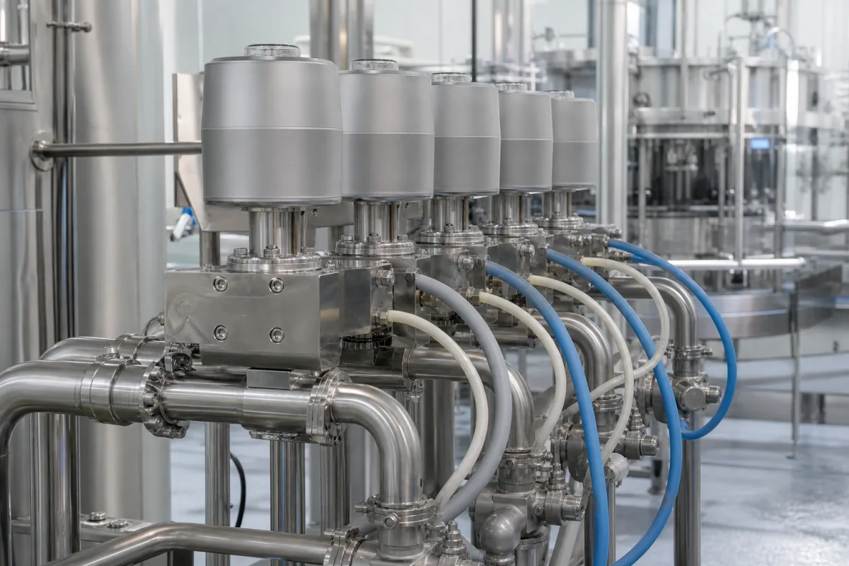
Representative product image. Confirm appearance and specifications with the manufacturer.

Product Specifications

Technical details and manufacturing context for Actuator Interface

Definition
An actuator interface is a critical component within beverage filling valve assemblies that serves as the communication bridge between the actuator mechanism and the electronic control system. It translates control signals into precise mechanical movements for valve operation, ensuring accurate beverage filling volumes and timing. This interface typically includes electrical connectors, signal processing circuits, and mechanical mounting points that enable seamless integration between automated control systems and the physical valve actuation components. In a typical beverage filling line, the actuator interface is mounted on or near the valve assembly, providing a standardized connection point for the control system's wiring and the actuator's power and feedback lines. The interface's internal circuitry conditions the incoming signals, which may include voltage or current levels, to match the actuator's requirements. It may also incorporate protection features such as surge suppression or isolation to safeguard sensitive electronics from industrial electrical noise. The mechanical mounting points ensure precise alignment of the actuator with the valve stem, which is essential for consistent valve stroke and sealing. The interface is designed to withstand the demanding conditions of beverage production, including exposure to moisture, cleaning agents, and temperature variations. Materials commonly used include stainless steel for structural integrity and corrosion resistance, engineering plastics for electrical insulation and lightweight support, and copper alloys for reliable electrical conductivity. The interface's dimensions and connector specifications are critical for proper integration and are typically defined by the equipment manufacturer. When selecting or replacing an actuator interface, it is essential to verify the exact model-specific dimensions, connector types, and signal compatibility with the existing control system and actuator. Always consult the original equipment manufacturer or a qualified supplier to confirm that the interface meets the required specifications for your specific filling valve assembly. Regular inspection of the interface's connectors, seals, and mounting hardware is recommended to prevent loose connections or corrosion that could lead to valve malfunctions. In the event of communication errors or erratic valve behavior, the interface should be checked as a potential failure point, along with the actuator and control system. Proper installation and maintenance of the actuator interface are vital for the reliable and accurate operation of beverage filling equipment.
Working Principle
The actuator interface receives electrical control signals from the filling machine's PLC or control unit, processes these signals through internal circuitry, and transmits them to the actuator. It may include signal conditioning, amplification, or conversion functions to ensure the actuator receives appropriate power and control commands. The interface also provides feedback signals from the actuator back to the control system, enabling closed-loop control of the filling process. This bidirectional communication allows the control system to monitor valve position and performance, making adjustments as needed to maintain filling accuracy.
Common Materials
Stainless Steel, Engineering Plastic, Copper Alloy
Technical Parameters

What to specify in your RFQ

  • Interface mounting dimensions and connector specifications in mm

These are the quantities to specify to the manufacturer when sizing or requesting a quote. The manufacturer's own documentation governs the exact figures and applicable standard.

Components / BOM
  • Electrical Connector Part
    Provides secure electrical connection between control system and actuator
    Material: Stainless Steel
  • Signal Conditioning Circuit
    Processes and conditions control signals for actuator compatibility
    Material: PCB with electronic components
  • Mounting Bracket Part
    Secures the interface to the valve assembly structure
    Material: Stainless Steel
  • Feedback Signal Circuit
    Carries actuator position back to the control system, which is what makes the loop closed.

Applied To / Applications

This component is essential for the following industrial systems and equipment:

Industrial Ecosystem & Supply Chain Structure

Complementary Systems
Downstream Applications
Specialized Tooling

Application Fit & Sizing Matrix

Operational Limits
pressure: 0 to 10 bar
flow rate: 0 to 100 L/min
temperature: -10°C to 80°C
slurry concentration: 0 to 30% solids by weight
Media Compatibility
✓ Carbonated beverages ✓ Non-carbonated liquids (water, juice) ✓ Food-grade cleaning solutions
Unsuitable: Abrasive slurries with high particulate content
Sizing Data Required
  • Actuator torque/force requirement
  • Control signal type (e.g., 4-20mA, 0-10V, digital)
  • Required response time/cycle frequency

Reliability & Engineering Risk Analysis

Failure Mode & Root Cause
Seal degradation
Cause: Chemical incompatibility with process media or environmental contaminants leading to swelling, hardening, or cracking of elastomeric seals, resulting in fluid leakage and loss of pressure integrity.
Electrical connection failure
Cause: Vibration-induced fatigue, corrosion from moisture ingress, or thermal cycling causing loose terminals, broken wires, or short circuits in signal/power connections, disrupting control signals or power supply.
Maintenance Indicators
  • Unusual hissing or buzzing sounds indicating air/fluid leaks or electrical arcing
  • Erratic or sluggish movement during operation, suggesting internal binding, contamination, or control signal issues
Engineering Tips
  • Implement regular preventive maintenance including seal inspections, lubrication of moving parts per manufacturer specs, and verification of electrical connection integrity using torque checks and thermal imaging.
  • Install protective measures such as environmental seals, conduit for wiring, and proper filtration of pneumatic/hydraulic fluids to prevent contamination and moisture ingress.

Indicative industry ranges for design and RFQ preparation. Confirm the exact figures and applicable standard with the manufacturer before specifying.

Compliance & Manufacturing Standards

Applicable Standards
ISO 15552: Pneumatic fluid power - Standard cylinders ANSI/B93.5M: Hydraulic fluid power - Cylinders DIN ISO 6431: Pneumatic cylinders - Mounting dimensions

Quoted from the published standard.

Manufacturing Precision
  • Bore diameter: +/-0.02 mm
  • Rod straightness: 0.05 mm per 300 mm length
Quality Inspection
  • Pressure testing for leakage (e.g., 1.5x operating pressure)
  • Dimensional verification with CMM (Coordinate Measuring Machine)

Manufacturers of Actuator Interface

Manufacturer profiles associated with Actuator Interface.

Sourcing Actuator Interface from China?
Tell us your specification and target quantity — we will match it against manufacturer records and come back with the factories that fit.
Request manufacturers We manufacture this

Manufacturer listings support early research and capability understanding. They are not certification, ranking, or transaction guarantees.

Technical documentation
Request current drawings, revision history, and a signed specification sheet.
Manufacturing capability
Verify equipment lists, process limits, capacity, and representative production evidence.
Inspection readiness
Confirm test methods, calibrated equipment, sampling plans, and traceable reports.
Supplier transparency
Check the legal entity, factory address, ownership, certifications, and direct contacts.

CNFX does not score or rank suppliers. Buyers must verify all claims and documents with the legal manufacturer before ordering.

Supply Chain Compatible Machinery & Devices

Automated Beverage Container Pressure Testing System

Automated system for testing beverage container pressure resistance and seal integrity.

Explore Specs →
Automated Beverage Container Leak Detection System

The Automated Beverage Container Leak Detection System is an industrial device designed for integration into bottling or canning lines.

Explore Specs →
Automated Beverage Container Depalletizing Machine

Industrial machine that automatically removes beverage containers from pallets for production line feeding

Explore Specs →
Regeneration Section

A dedicated section within an industrial system designed to restore or renew the functional properties of materials, media, or components through controlled processes.

Explore Specs →

Frequently Asked Questions

What is the primary function of an actuator interface in a beverage filling valve?

The actuator interface acts as the communication bridge between the actuator and the control system. It receives control signals from the PLC, conditions them, and sends them to the actuator to operate the valve. It also transmits feedback from the actuator back to the control system for closed-loop control.

What materials are commonly used for actuator interfaces?

Common materials include stainless steel for structural strength and corrosion resistance, engineering plastics for insulation and lightweight support, and copper alloys for electrical conductivity. The specific materials used depend on the application and manufacturer design.

How do I ensure the actuator interface is compatible with my existing system?

You must verify the interface's mounting dimensions, connector specifications, and signal compatibility with your control system and actuator. Always consult the original equipment manufacturer or a qualified supplier to confirm that the interface meets the required specifications for your specific valve assembly.

What are common signs of a failing actuator interface?

Common signs include erratic valve operation, communication errors between the control system and actuator, loose connections, or visible corrosion on connectors. If you experience such issues, inspect the interface and its connections, and consider testing or replacing it as needed.

Data Basis

Editorial classification, named public sources where available, and source-reviewed manufacturer records.

Preliminary Technical Classification
This page supports structured research, RFQ preparation, and supplier evaluation. It does not replace buyer-led supplier qualification, standards review, or technical approval.
Buyer enquiry

Request manufacturing insight for Actuator Interface

Ask for use case, specification boundaries, supplier type, and RFQ preparation information for this product.

Where it goes
Straight to the CNFX editorial desk, and to the manufacturer if this product is linked to a claimed profile. Nothing is broadcast to a supplier list.
Your details stay here
We do not sell or rent enquiry data, and we do not add you to a mailing list. Used only to answer this request.
No commission, no middleman
CNFX is a directory. We take no cut of any order and never negotiate on a supplier's behalf.
What we don't claim
A listing is not an endorsement. Qualify every supplier and verify every figure yourself before ordering.

Your business information is used only to process this request.

Thank you! Your message has been sent. We'll respond within 1–3 business days.
Sorry, we couldn't send your message. Please try again, or email us at contact@cnfx.com.

Need to Manufacture Actuator Interface?

Compare manufacturer profiles with relevant product and process capability.

Previous Product
Vacuum Gripper End-Effector
Last Product
Get QuotesChat