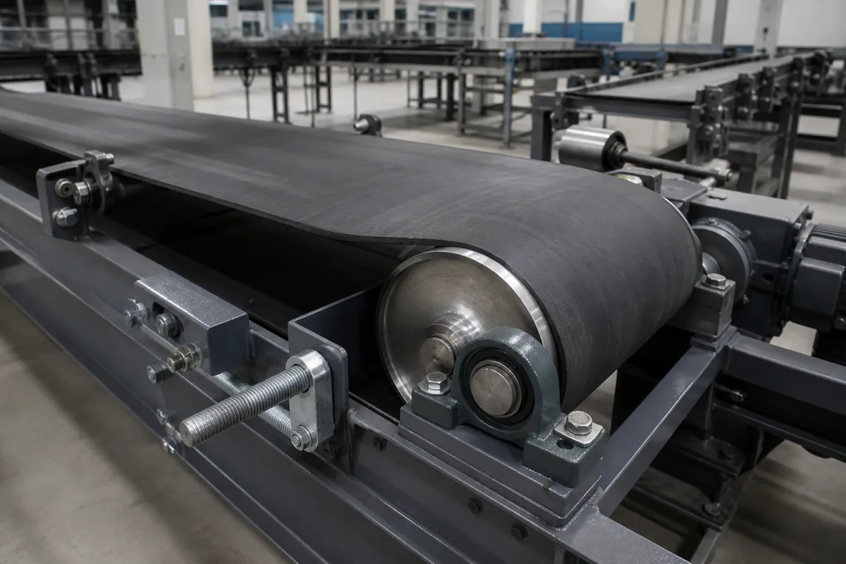
Conveyor belt roller: drive and end drums with screw take-up for flat-belt conveyors
Drive and end drums for flat-belt unit-goods conveyors · drum diameter and crown, lagging hardness, screw or force-dependent take-up, 1% take-up range
In a flat-belt conveyor for unit goods, the belt runs round a drive drum and an end (tail) drum; the end drum can be mounted in adjustable bearings so that screws can move it and tension the belt. The drums set how well the belt tracks, how much pull the drive can transmit and how tightly the belt must be stretched. Ask three things first: what drum diameter and crown the belt type allows, whether the drive drum needs lagging, and how much take-up travel the end drum has.
Drive, end (tail), deflection and snub drums for flat-belt unit-goods conveyors, with their bearings and screw or force-dependent take-ups, specified by diameter, crown or conicity, surface or lagging and take-up range. Complete bulk-handling troughed belt conveyors and flat or modular belt conveyors are covered on the Belt conveyor page. Conveyor belting on its own, troughing idlers for bulk material, and gravity or powered rollers of roller conveyors are outside this page except where compared.
CNFX editorial research · Sources checked October 12, 2026 · 4 sources
Size the drum, choose crown or cylinder, and decide on lagging
Forbo Siegling's machine-design recommendations for its Transilon belts say drum diameters should always be as large as possible; the minimum is set by the effective pull to be transmitted and by the belt's flexural properties (dmin in each belt data sheet). In wide conveyors, drums that are too small deflect too much, creasing and mistracking the belt. Forbo recommends a drive drum with a cylindrical centre section of half the belt width and tapered edges, and tabulates conicity by drum diameter: for single-ply belts 0.5 mm up to 200 mm diameter, 0.8 mm from 200 to 500 mm and 1.0 mm above 500 mm. [1]
On the drive drum, lagging improves friction; Forbo asks for polyurethane lagging of at least 85 Shore A at 20 °C or abrasion-resistant rubber above 65 Shore A, bare drum faces with roughness Rz ≤ 25 µm, and rollers with small arcs of contact (up to 15°) may be half dmin. [1] Its calculation brochure tabulates the drive factor C1 for a smooth steel drum with V3/U2-type underside coatings at 1.5 dry and 3.7 wet for 180° wrap, against 1.4 and 1.8 for a lagged drum, showing the effect of lagging in wet running. [2]
Interroll's deflection drum with integrated bearings, built to the same dimensions as its drum motors, comes crowned or cylindrical: the 113 mm size measures 113.5 mm at the centre and 112 mm at the edges when crowned, and 112 mm when cylindrical, with IP69k protection, NBR internal and PTFE external shaft seals, and laggings for friction-drive, modular plastic and positive-drive belts. [3] Editorial calculation: 113.5 − 112 = 1.5 mm on diameter, a crown of 0.75 mm on radius.
Give the supplier the belt type and its dmin, belt width and speed, drive position (head, tail or centre), arc of contact, effective pull or motor power, wet or dry running, drum face width, crown or cylinder, lagging type and hardness, bearing and shaft arrangement, and the take-up travel needed.
02
Set the take-up travel on the end drum
Forbo explains that the contact pressure on the drive drum comes from elongating the belt, and the end drum can serve as the tensioning drum if screws can move it while keeping it parallel to the drive drum. Elongation at fitting of about 0.2% to 1% is sufficient depending on load, and it gives a take-up range of about 1% of the belt length as adequate; the range must also cover belt length tolerances and margins for temperature or stop-and-go running. [2]
The same brochure lists recommended elongation at fitting by belt fabric: 0.3–1.0% for standard polyester, 0.2–0.8% for high-tech polyester, 0.15–0.8% for aramid and 1.5–5.0% for elastic fabrics. [2] Forbo adds that a fixed screw take-up cannot compensate for belts that stretch at start-up, under unequal loads or with temperature, recommends force-dependent take-ups (weight, pneumatic, hydraulic or spring) in high and fluctuating temperatures, and on very long, heavily loaded conveyors places the take-up directly after the drive drum. [1]
Editorial calculation: on a conveyor with a 12 m belt, about 1% gives 120 mm of screw travel on the end drum, before allowing for length tolerance; an elastic-fabric belt fitted at up to 5% would need far more, which is a reason to check the belt type before fixing the bearing slots.
03
Published drum and take-up figures in one place
Belt type sets these limits, so values are tied to the belt maker's data.
Item
Published value
Source
Conicity, single-ply belt
0.5 mm (≤200 mm drum); 0.8 mm (200–500 mm); 1.0 mm (>500 mm).
Paste it into your enquiry below or into an email to a maker, then replace every bracket.
Belt: [type; width; dmin; k1%; length]
Drive: [head, tail or centre; arc of contact; effective pull or motor power; wet or dry]
Drums: [diameter; face width; crown or cylinder; lagging and hardness]
Bearings: [pillow block or integrated; shaft; seals]
Take-up: [screw or force-dependent; travel]
Documents: [drawing; runout and crown tolerance]
1 company lists this product among what they make. Company figures are quoted from each
company's own website; every card states where the relationship came from.
Dongguan Smart Automation Components Co., Ltd.
Manufacturing site to be confirmed for the order
Lists belt conveyor drum motors in 80–600 mm diameters with plain, rubber-lagged or ceramic-coated shells, alongside conveyor rollers.
Explore company information and manufacturing capabilities, then discuss the scope of your project with a relevant supplier.
Share this page
Compiled and source-reviewed by the CNFX editorial team.
Each manufacturer above links to the page on that company's own website where the product is listed, with the date we checked it. How we source and review
· Page last updated 13 October 2026
Buyer questions
How much take-up travel does a flat conveyor belt need?
Forbo Siegling says that with elongation at fitting of about 0.2–1%, a take-up range of about 1% of the belt length is adequate, plus allowance for length tolerance. [2]
Should the drive drum be lagged?
Lagging raises friction; Forbo's tables give a smooth steel drum a C1 factor of 3.7 wet at 180° against 1.8 for a lagged drum, and it asks for PU lagging of at least 85 Shore A. [2][1]
How large is the crown on a conveyor drum?
Forbo tabulates 0.5–1.0 mm conicity for single-ply belts by drum size; Interroll's crowned 113 mm drum is 113.5 mm at the centre and 112 mm at the edge. [1][3]
Sources and what still needs a direct check
Sources checked 2026-10-12. Forbo Siegling (belt maker) gives drum and take-up guidance for its belts; Interroll and SROLLMART describe their own drums. The belt maker's data for the belt fitted governs.