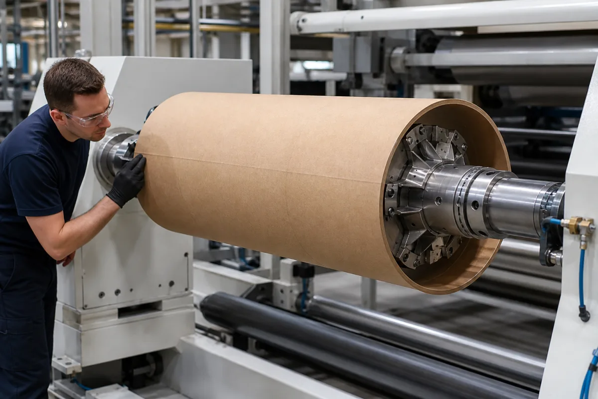
Core chucking system: shaftless lug chucks that grip inside the core, and safety chucks that carry a core shaft
Core chucks and safety chucks for unwinds and rewinds · Shaftless lug chucks that expand inside 3- to 12-inch cores, core adapters, torque until the core slips, and square-journal safety chucks that carry a core shaft
This page covers the parts of an unwind or rewind that hold the core: shaftless core chucks that enter each end of the core and expand lugs or leaves against its inside, with adapters for larger cores, and safety chucks that hold the square journals of a core shaft. Ask three things first: the core inside diameter and material, the torque the chucks must pass before the core slips with your brake or drive arrangement, and the roll weight per pair of chucks at your speed.
Core chucks that grip inside a winding core, including air-, torque- and spring-actuated lug and leaf chucks with core adapters, and safety chucks that hold the square journals of a core shaft, for unwinds and rewinds. Tension measurement and control on the unwind or rewind, with load cells, dancers, brakes and controllers, is covered on the Tension control page. Air shafts, laboratory rock-core holders and plastic core holders for film dispensers are outside this page.
CNFX editorial research · Sources checked October 12, 2026 · 4 sources
Lugs that expand inside the core: air-actuated, torque-actuated and spring-engaged chucks
Maxcess describes its Raptor air-powered lug chucks for shaftless unwinds and rewinds on high-speed printing, laminating and sheeting lines, including flying or zero-speed splicers: wide-footprint lugs grip the inside of the core without damaging it, lugs are retracted mechanically with a secondary pneumatic retraction as backup, and expansion is concentric within 0.381 mm (0.015 in) TIR. Its Raptor torque chucks for corrugating, sheeting, paper finishing and laminating take tool-less adapter changes in less than 5 seconds on the machine. [1][2]
Montalvo describes its GRPA chuck as a heavy-duty steel core chuck whose air-activated pistons mechanically drive ramped expanders outward for centring, with expanding leaves or lugs and flange or shaft-extension mounting. Adapters slip over the base chuck and lock on three locating pins to take larger cores and transmit torque. Versions are air-actuate/spring-retract or spring-engage/air-retract, actuated through a rotary union or an air gun, and an optional GR20PTA design is offered for extreme torque, which Montalvo notes is effective with steel cores and during E-stops. [4]
Editorial note: on a spring-engage/air-retract chuck the core stays gripped if air is lost; on an air-actuate version, ask how grip is held through an air failure or an E-stop.
Give the supplier the core inside diameters and wall material (fibre or steel), roll weight and width, speed, unwind or rewind duty, splicer type, brake or drive at each end, available air pressure and how the chuck is mounted on the machine.
02
Torque until the core slips depends on two brakes, fibre core quality and 80 psi
Maxcess rates Raptor chucks as maximum allowable torque until the core slips, assuming two chucks with two brakes or drives and good-quality fibre cores, and 80 psi for the air chuck; with only one brake, for example with a dummy chuck at the other end, the values are halved. [1][2]
Editorial calculation: with one brake, the 3-inch Raptor air chuck's 795.3 N·m becomes about 398 N·m, below the 543.3 N·m the 3-inch torque chuck is rated for with two brakes. Adapters extend both chuck families to cores up to 12 in (304.8 mm). [1][2]
Safety chucks on a core shaft: square journal size sets roll weight, torque and speed
Where the roll is wound on a shaft, Maxcess's Boschert safety chucks carry the shaft's square journals and pass brake torque; the manual C and VT series close on their own if the operator neglects to, and the automatic A and P series open and close remotely with a redundant mechanical lock against opening in operation. Ratings below are per pair of chucks; VT-2 and VT-7 chucks take 0.8 times the weight and 0.7 times the torque. [3]
Boschert's manual range runs from a Mini size at 150 kg per pair to 170–230 mm journals at 64,000 kg per pair; the automatic A40/P40, A50/P50 and A80 chucks carry 1,600, 2,800 and 7,000 kg per pair. [3]
Core bore, grip diameter and runout to put in a chuck order
Core inside diameter comes first: it fixes the base chuck or adapter, and each Raptor size has its own collapsed and expanded diameters around the nominal core bore. [1][2]
Field
Published value or dependency
Ask the supplier for
Clamping Diameter Range (mm)
Base chucks for 76.2 and 152.4 mm cores; adapters up to 304.8 mm. [1]
Explore company information and manufacturing capabilities, then discuss the scope of your project with a relevant supplier.
Share this page
Compiled and source-reviewed by the CNFX editorial team.
Each manufacturer above links to the page on that company's own website where the product is listed, with the date we checked it. How we source and review
· Page last updated 13 October 2026
Buyer questions
How much torque can a core chuck pass?
Maxcess rates Raptor torque chucks at 543.3 N·m for 3- and 4-inch cores and 3,599.8 N·m for 6-inch cores until the core slips, with two brakes and good-quality fibre cores; with one brake the value is halved. [2]
What is the difference between a core chuck and a safety chuck?
A core chuck enters the core and expands lugs or leaves against its inside, as on Maxcess Raptor and Montalvo GRPA chucks; a safety chuck such as Boschert's holds the square journals of a core shaft. [1][4][3]
How accurately does an expanding core chuck centre the core?
Maxcess states that Raptor chucks expand concentrically within 0.381 mm (0.015 in) TIR. [1]
Sources and what still needs a direct check
Sources checked 2026-10-12. Maxcess describes its own Raptor and Boschert chucks in product sheets; Montalvo describes its own GRPA chuck.