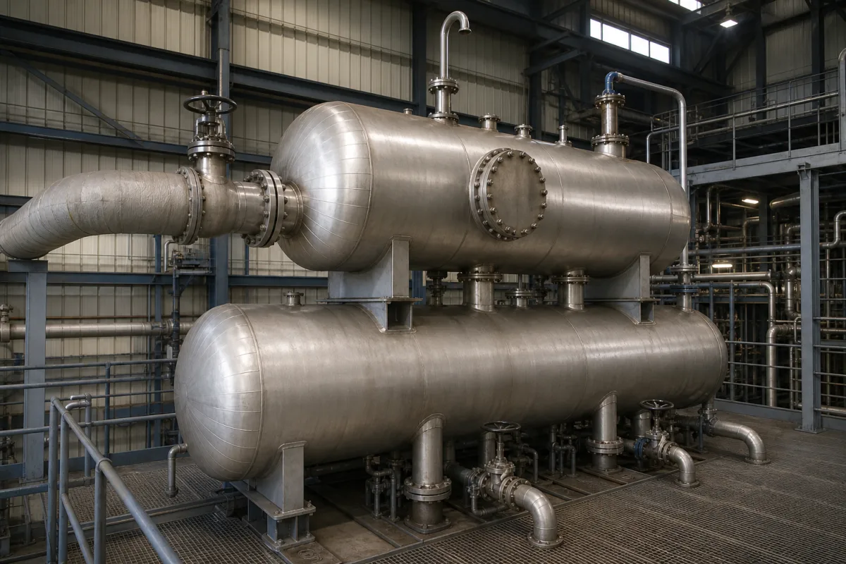
For boiler feedwater, the purchase decision starts with the outlet oxygen guarantee and the conditions under which it must hold. Water temperature alone does not prove deaeration: steam must contact the water, released gases must leave through the vent, and the storage and feed-pump arrangement must support the plant’s changing demand.
CNFX editorial research · Sources checked October 9, 2026 · 6 sources
ABMA’s 2011 white paper describes mechanical removal to no more than 7 ppb dissolved oxygen. Use this as an attributed performance reference, then agree the boiler’s actual water-chemistry requirement and acceptance test; it is not a universal limit for every steam plant [1].
7 ppb is a mechanical result; chemicals are a supplement
Chemicals can react with oxygen and carbon dioxide, but mechanical deaeration removes rather than transforms the gases; ineffective mechanical deaeration shows up as extra chemical feed and operating cost [1]. Mechanical deaeration can also remove free CO₂ to non-detectable levels, though chemically bound CO₂ may remain depending on condensate pH [1].
Write the load range into the guarantee
Burnham’s suggested specification calls for 0.005 cc/L (7 ppb) oxygen or less and zero measurable CO₂ across 0–100% of rated capacity. It is a procurement specification with blanks for the selected equipment, not a test certificate for an unidentified unit. Define inlet conditions, stable operation, sampling point and test method in the order [2].
An atmospheric feedtank is a different starting point
Spirax Sarco distinguishes atmospheric feedwater heating from pressurised deaeration. Its tutorial gives about 2 mg/L residual oxygen for a feedtank at 85–90 °C, with further treatment needed. A hot tank or a “deaerator head” label alone does not establish a 7 ppb outlet guarantee [6].
02
Heating releases gases; contact and venting finish the job
ABMA describes two stages in modern thermal deaerators: preheating by direct steam contact, followed by further steam–water contact to remove residual oxygen. The tray, submerged-injection and scrubber arrangements below accomplish that second task differently [1].
Heat to full saturation
Bring water close to the saturation condition for the operating pressure. The theoretical gas-solubility argument does not mean an actual outlet contains zero oxygen [1].
Give water and steam intensive contact
So that gases are scrubbed out in a reasonable time [1].
Dilute the released gases with steam
To keep their partial pressure above the water low [1].
Vent the gases with minimal steam loss
Vent steam is the main thermal loss of a modern deaerator [1].
Second-stage design
How it finishes deaeration
Typical arrangement
Tray cascade
Pre-heated water flows down a tray stack against rising steam [1]
A separate deaerator vessel above a storage tank, or a single-tank version where little storage is needed [1]
Under-water steam injection
Steam injected below the water level in the storage tank scrubs residual oxygen [1]
ABMA explains why self-adjusting spray devices maintain their pattern across changing flow more effectively than a fixed opening. Ask how the offered design maintains its outlet guarantee at your minimum flow, rather than specifying a nozzle name alone [1].
03
Follow water through the distribution, contact and storage sections
This functional component reference uses Bryan’s DTA tray arrangement and Burnham’s spray-scrubber specification. They are different constructions; it is not a manufacturing BOM with interchangeable parts.
Component
What it does
Material and configuration evidence
Spray device / distribution assembly
Spreads incoming water to expose it to steam.
Bryan depicts stainless spray tubing; Burnham specifies a self-adjusting stainless valve. These are different distributing devices, not a single replacement item [3][2].
Deaeration / scrubbing section
Provides further steam–water contact after preheating.
Bryan specifies welded 304L trays and surfaces touching undeaerated water. Burnham instead describes a thin-film scrubbing section and 304L collection box. Do not assign the shell’s material to these internals [3][2].
Storage section / feedwater tank
Holds treated water between the deaerating stage and boiler feed pumps.
The DTA lower vessel has separate high, low and overflow levels. The cited documents do not establish its shell alloy grade; request the vessel material specification and data report [4].
Vent condenser and vent path
Recovers heat from escaping steam while allowing non-condensable gases to leave.
Bryan shows an internal stainless direct-contact vent condenser and vent pipe. This is not evidence that every deaerator includes a separate external condenser, and the vent must remain functional [3][5].
04
Match operating pressure to the available steam and return flows
ABMA’s 2011 examples below describe plant arrangements, not mandatory setpoints. It recommends economical available steam and positive venting; its 3 psig minimum recommendation belongs to that discussion. Vacuum designs need a separate means of removing the released gases [1].
Burnham’s suggested spray-scrubber package operates at 5–15 psig and 228–250 °F. Those are operating conditions; its stated maximum working rating is 50 psig at 300 °F. Do not order or operate from a pressure number without identifying which rating it represents [2].
05
Define the package: storage, vessel, trim and pumps
Separate the vessel, storage, trim and feed-pump scope in the quotation. Burnham’s suggested specification gives one package example; the project’s approved drawings and equipment list must identify what is actually supplied [2].
Storage
ABMA describes ten minutes as a planning allowance, with shorter and longer arrangements. Burnham specifies at least ten minutes to overflow. Identify the level basis and usable reserve instead of treating every tank gallon as available boiler feedwater [1][2].
Pressure vessel
Burnham’s example calls for ASME VIII Division 1 construction, a 50 psig maximum working rating at 300 °F and 1/16-inch corrosion allowance on the U-1 report. This is its suggested specification, not the required rating of every deaerator [2].
Undeaerated-water contact surfaces
Burnham specifies stainless surfaces in contact with undeaerated water and removable stainless spray valves. This does not establish a stainless pressure shell or the material of every wetted component [2].
Controls and trim
High and low level alarms, overflow trap, make-up valve with 4–20 mA level control, pressure-reducing and relief valves, vacuum breaker and an orificed vent valve [2].
Feed pumps and stand
Burnham sets stand height by feed-pump NPSH requirements and includes a project-specific pump schedule. Confirm flow, head, hot-water suction conditions and piping losses with the pump supplier; the stand is part of the hydraulic arrangement, not just a shipping support [2].
Inspection
ABMA’s 2011 paper recommends annual comprehensive inspection subject to the authority having jurisdiction. Establish the current legal and manufacturer inspection plan for the actual vessel [1].
06
Overflow volume is not the water reserve between control levels
The DTA-70 provides a concrete example of why the level schedule belongs in the enquiry. Bryan’s 2015 Form 2007 lists the following tank contents; the earlier brochure lists a nominal 1,400-gallon storage capacity [4][3].
A dimensioned tank is not the complete installed envelope
Bryan’s May 2000 brochure lists DTA-70 dimensions of 176 × 60 × 180 inches, with the height explicitly excluding the stand. It also says stand height varies with pump and job conditions. Use the current certified assembly drawing for headroom, pump access and foundation planning [3].
DTA-70 level
Height from tank bottom
Water volume in 2015 drawing
Overflow
48 in
1,469 US gal / 5,560 L
High level
46 in
1,384 US gal / 5,238 L
Low level
6 in
80 US gal / 303 L
Source: Bryan Form 2007, effective May 15, 2015 [4]. The high-to-low difference is 1,384 − 80 = 1,304 US gallons. That arithmetic does not establish usable reserve or running time: agree the normal level, low-level pump shutdown and withdrawal rate for the actual system. The historic nominal storage figure and level-specific volumes are different quantities.
07
Specify the duty without borrowing an anonymous capacity range
Use the operating envelope and the selected configuration. Historical Bryan drawings and Burnham’s suggested specification below are reference examples, not a confirmation of a current factory build.
Field
How to specify or interpret it
Rated capacity
DTA-70 is listed at 70,000 lb/h in Form 2007. State maximum and minimum feedwater demand, including return-water conditions; boiler horsepower is a separate column, not the feedwater flow unit [4][1].
Operating pressure
Name the normal pressure, range and gauge/absolute basis. Burnham’s package example is 5–15 psig; a higher pressure is not by itself proof of a better oxygen result [2][1].
Operating temperature
Tie it to the pressure and the guaranteed operating condition. Burnham pairs its 5–15 psig range with 228–250 °F [2].
Oxygen-removal efficiency
Ask for inlet and outlet concentrations and test conditions. A percentage removal claim alone cannot establish the required outlet oxygen level [1].
Residual oxygen
Specify the guaranteed outlet concentration, load range and sampling/test method. Burnham’s suggested limit is 7 ppb; an acceptance guarantee must identify the offered unit [2].
Shell material
Request the pressure-shell specification separately from tray, spray and condenser materials. Bryan’s 304L statement for undeaerated-water contact surfaces does not identify every pressure-boundary part [3].
Design pressure
Request design data and the vessel’s maximum allowable working pressure. Burnham’s 50 psig maximum working rating is separate from its 5–15 psig operating range [2].
Design temperature
Specify it with the pressure rating. Burnham’s suggested maximum working rating is stated at 300 °F, not its normal feedwater temperature [2].
Water inlet temperature
Give each make-up and condensate stream’s temperature and flow, including cold starts and changes in return rate. These determine the heating duty [6].
Steam consumption
Obtain a heat/mass balance using the actual inlet streams and heating steam. Include vent and heat losses; the cited sources do not justify a single steam-per-tonne figure for the category [6].
Pressure drop
Identify the path: water inlet/distributor, steam control train or pump suction piping. Ask for the selected assembly’s losses at the specified flow; no universal deaerator pressure drop is established here [2][5].
Weight
Request dry, shipping and operating masses and support loads. The cited DTA tables do not supply a mass value; capacity does not establish foundation loading.
Footprint and height
Use the certified assembly envelope including the stand and service access. The older DTA dimensions exclude stand height and are stated as reference dimensions [3][5].
08
Track venting, level control and deposits together
Bryan’s tray-type manual, Form 2142 revised May 1, 2015, provides the following maintenance checkpoints. Confirm applicability to the unit’s serial number and current supplied instructions; these are not a commissioning procedure for every deaerator [5].
During operation
Its daily schedule calls for recording gauges and indicators, checking level controls and pump operation, and observing vent discharge. A steam plume indicates a vent path; it is not a dissolved-oxygen acceptance measurement [5].
When performance changes
Review pressure, temperature, inlet conditions and actual oxygen samples together. Closing the vent to hide steam loss can trap gases and impair deaeration [5][1].
At planned service
The manual calls for strainer checks monthly and spray-tube/tray inspection for scale or sludge annually, with more frequent cleaning where water quality requires it. Arrange intrusive work under the approved shutdown and isolation procedure [5].
Before return to service
Check the trays remain correctly aligned and level. Follow the equipment instructions for access-door sealing and control tests; the manual specifies a new ring gasket after opening the tray door [5].
09
Copy this RFQ and fill in the brackets
Paste it into your enquiry below or into an email to a maker, then replace every bracket.
Product: boiler feedwater deaerator, [tray / spray-scrubber / steam-injection], [one-tank / two-tank], quantity [units]
Feedwater duty: minimum [ ] / maximum [kg/h or lb/h], operating schedule [ ]
Outlet guarantee: dissolved O2 [ppb], CO2 [limit and measurement], load range [ ], inlet conditions [ ], test method and sample point [ ]
Steam supply: source [ ], available pressure and temperature [ ], deaerator operating pressure [psig / barg / bara]
Water streams: make-up [flow, temperature, chemistry]; condensate returns [flow, temperature, pressure, air exposure]
Storage: normal / high / low / overflow levels [ ]; usable reserve and required duration [ ]
Vessel: governing code and edition [ ], design pressure/temperature [ ], MAWP [ ], materials and corrosion allowance [ ]
Trim and pumps: level controls, alarms and shutdowns [ ]; vent/overflow/protection [ ]; pump flow/head/NPSH and stand [ ]
Documents: oxygen guarantee/test plan, vessel data report, heat balance, P&ID, certified dimensions/masses, supplied-parts list and maintenance instructions
Delivery to [country], target date [date]
1 company lists this product among what they make. Company figures are quoted from each
company's own website; every card states where the relationship came from.
Explore company information and manufacturing capabilities, then discuss the scope of your project with a relevant supplier.
Share this page
Compiled and source-reviewed by the CNFX editorial team.
Each manufacturer above links to the page on that company's own website where the product is listed, with the date we checked it. How we source and review
· Page last updated 13 October 2026
Buyer questions
How much oxygen should a deaerator leave in the water?
ABMA’s 2011 white paper describes mechanical deaeration to 7 ppb or less. Agree the actual boiler-feedwater requirement, inlet conditions, load range and acceptance test with the supplier; the benchmark is not a guarantee for every unit. [1]
Why not just use oxygen scavenger chemicals?
Chemicals transform oxygen in the water, but mechanical deaeration removes it; poor mechanical deaeration is paid for in extra chemical feed and operating cost. [1]
What pressure should my deaerator run at?
Choose the pressure with the available steam, venting arrangement and return-water conditions. ABMA’s 2011 examples include 5–10 psig on reduced boiler steam and 15–60 psig in cogeneration. Its 3 psig positive-venting recommendation is guidance in that context, not the operating range of every design. [1]
How much storage do I need?
ABMA uses about ten minutes as a planning reference, with plant-dependent variations. Specify which water levels define the reserve and the relevant feedwater demand: overflow volume and usable operating reserve are different. [1][4]
Which code covers the deaerator vessel?
ABMA's 2011 white paper says deaerator pressure vessel construction is “commonly covered by ASME Boiler and Pressure Vessel Code, commonly Section VIII, Division I”, and that integral HRSG deaerators are built to the boiler codes rather than as pressure vessels; confirm the code with the vessel supplier. [1]
Sources and what still needs a direct check
Sources checked 2026-10-09. Standards bodies and regulations define the requirements; manufacturer pages show published ranges for those models only. CNFX does not certify products or suppliers.
The Heat Exchange Institute standard and full ASME construction code were not read. Public manufacturer documents and the dated ABMA paper are attributed guidance, not confirmation of compliance.
Bryan’s currently linked references are dated 2000 and 2015. Obtain current drawings, performance guarantees and instructions for the offered build.
No source-checked Chinese deaerator manufacturer is currently linked to this product. Reference equipment does not establish a Chinese supply relationship.
Confirm water chemistry, sample conditioning, test method, minimum-load performance, usable reserve, pump suction conditions and current inspection requirements for the project.
Buyer enquiry
Request manufacturing insight
for Deaerator
Ask for use case, specification boundaries, supplier type, and RFQ preparation
information for this product.
Where it goes
Straight to the CNFX editorial desk, and to the manufacturer if this product is
linked to a claimed profile. Nothing is broadcast to a supplier list.
Your details stay here
We do not sell or rent enquiry data, and we do not add you to a mailing list.
Used only to answer this request.
No commission, no middleman
CNFX is a directory. We take no cut of any order and never negotiate on a
supplier's behalf.
What to include
Share your product specifications, quantity, destination and target delivery date.
Need to Manufacture Deaerator?
Compare manufacturer profiles with relevant product and process capability.