Coating Dispensing System
View system integration details
This page explains how Dispense Pump/Valve is classified within Machinery and Equipment Manufacturing. Technical values and manufacturer relationships are research references; confirm the current specification and supplier evidence for each order.
A precision fluid control component that meters and directs coating materials in dispensing systems.
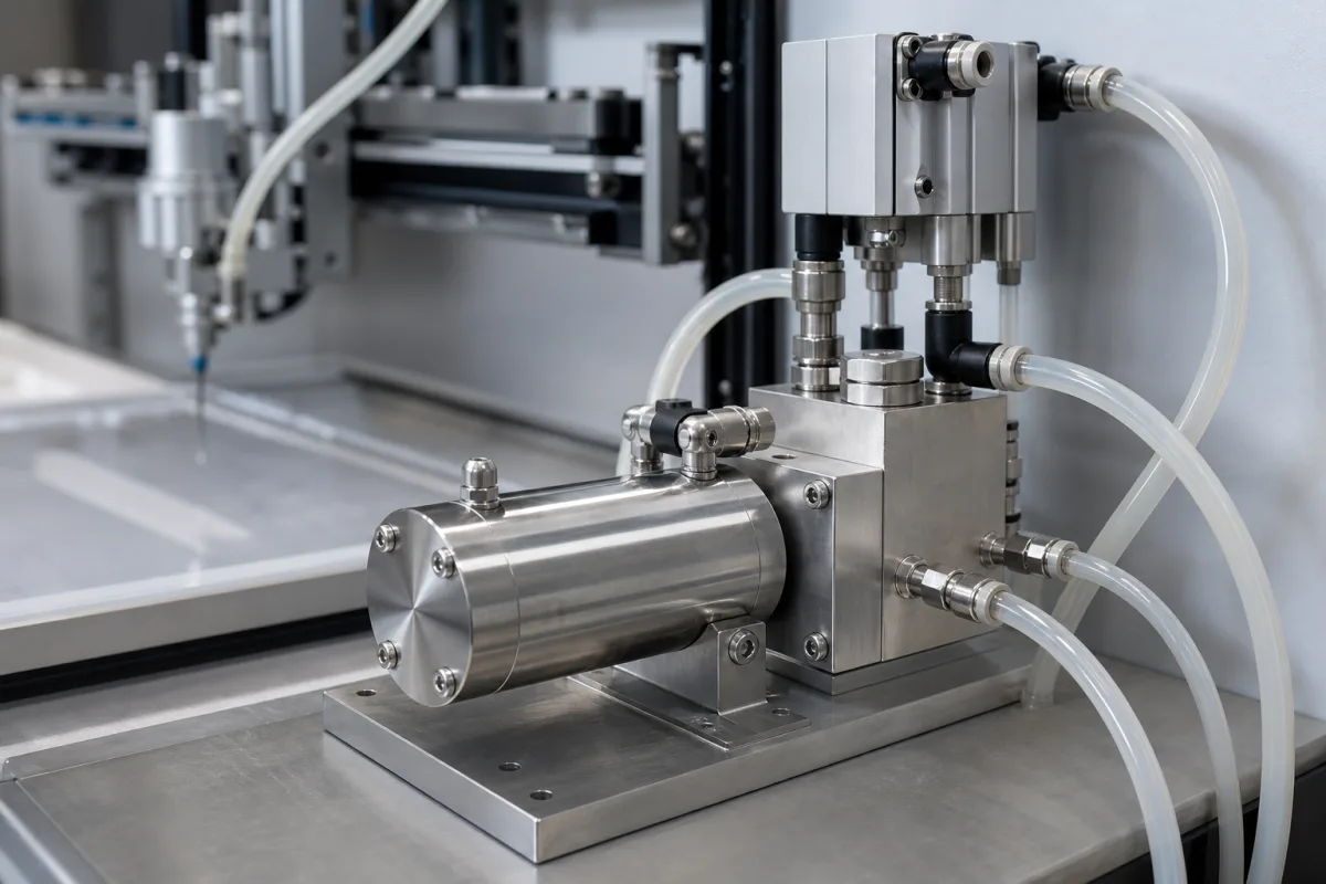
Technical details and manufacturing context for Dispense Pump/Valve
| Parameter | Typical range | Notes & selection driver |
|---|---|---|
| Flow Rate | 0.5–5 L/min | Adjustable via stroke length and frequency |
| Dispensing Volume per Cycle | 0.1–50 mL | Depends on pump size and adjustment |
| Dispensing Accuracy | ±1 % | Repeatability of dispensed volume |
| Max Fluid Temperature | 80 °C | Above this, seals degrade |
| Ambient Temperature Range | -10–50 °C | Non-condensing |
| Viscosity Range | 1–10000 mPa·s | Higher viscosity may require larger pump |
| Voltage | 24 ±10% V DC | For solenoid actuation |
| Power Consumption | 10–30 W | Depends on actuation type |
| IP Rating | IP54–IP65 | Protection against dust and water jetsIEC 60529 |
| Body Material | 316 SS | Corrosion-resistant for chemical mediaASTM A276 |
| Seal Material | PTFE | Chemical compatibilityASTM D4894 |
| Weight | 1.5–3.5 kg | Varies with size and actuation |
| Connection Size | 1/4–1/2 inch | BSP threadISO 228-1 |
Ranges are indicative industry figures for RFQ preparation, not a supplier commitment. Confirm every value and standard with the legal manufacturer before ordering.
| pressure: | 0 to 100 psi (7 bar) |
| flow rate: | 0.1 to 100 mL/min |
| temperature: | -20°C to 150°C |
| slurry concentration: | Up to 30% solids by weight |
Indicative industry ranges for design and RFQ preparation. Confirm the exact figures and applicable standard with the manufacturer before specifying.
Quoted from the published standard.
A practical evidence checklist for RFQ preparation and supplier evaluation.
Compare the published product scope and source details, then include your specifications and quantity in an enquiry.
Manufacturer profiles associated with Dispense Pump/Valve.
Explore company information and manufacturing capabilities, then discuss the scope of your project with a relevant supplier.
Ask for use case, specification boundaries, supplier type, and RFQ preparation information for this product.
A dispense pump provides the motive force to move fluid, while a dispense valve controls the flow direction and on/off state. In a combined dispense pump/valve, both functions are integrated into one component, allowing precise metering and directional control in a single unit.
Selection depends on factors such as fluid viscosity, required flow rate, dispensing volume per cycle, accuracy, operating pressure, temperature, and chemical compatibility. Review the reference parameters (e.g., flow rate 0.5–5 L/min, viscosity 1–10000 mPa·s) and verify with the manufacturer for your specific media and process conditions.
Regular maintenance includes checking seals for wear, cleaning fluid paths to prevent clogging, and verifying calibration of dispensing volume and accuracy. Monitor for signs of leakage, inconsistent flow, or pressure drops, which may indicate seal degradation or valve wear. Follow the manufacturer's maintenance schedule.
The viscosity range is 1–10000 mPa·s, but higher viscosity may require a larger pump or special design. Confirm the pump's capability for your specific material, as very high viscosities can affect flow rate and accuracy. Consult the manufacturer for guidance.
This component is essential for the following industrial systems and equipment:
Commonly used trade names and technical identifiers for Dispense Pump/Valve.
Editorial classification, named public sources where available, and source-reviewed manufacturer records.
Compare manufacturer profiles with relevant product and process capability.