Editorial Technical Reference

Drive Mechanism (e.g., Ball Screw, Hydraulic Cylinder)

This page explains how Drive Mechanism (e.g., Ball Screw, Hydraulic Cylinder) is classified within Machinery and Equipment Manufacturing. Technical values and manufacturer relationships are research references; confirm the current specification and supplier evidence for each order.

Technical Definition & Core Assembly

A mechanical or hydraulic system that converts rotational or fluid power into precise linear motion to position and control the lance.
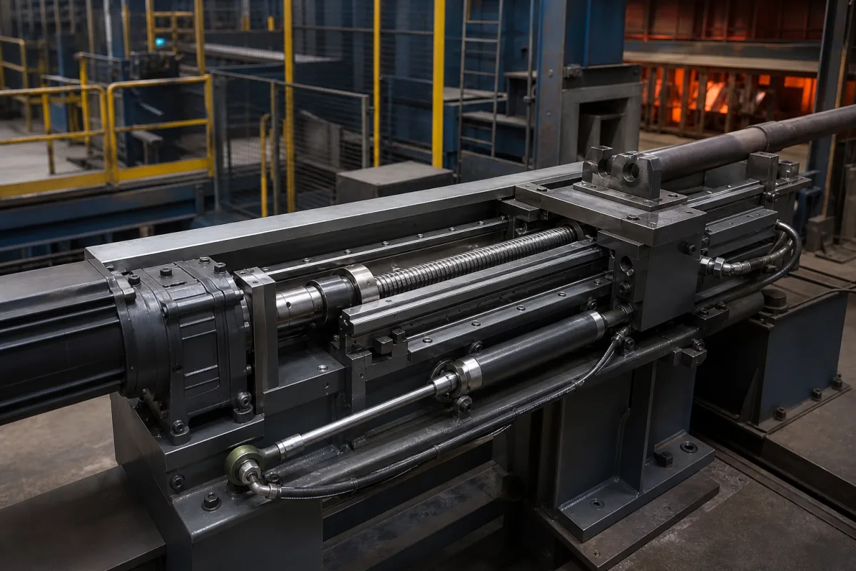
Representative product image. Confirm appearance and specifications with the manufacturer.

Product Specifications

Technical details and manufacturing context for Drive Mechanism (e.g., Ball Screw, Hydraulic Cylinder)

Definition
The drive mechanism is the core actuation component of a Lance Manipulator, responsible for translating control signals into accurate linear displacement of the lance. It determines the precision, speed, force, and repeatability of the lance's extension and retraction movements, which are critical for operations like injection, sampling, or measurement in industrial furnaces or vessels. This component is typically a ball screw or hydraulic cylinder, each offering distinct characteristics. Ball screw mechanisms convert electric motor rotation into linear motion via recirculating ball bearings, providing high precision and repeatability. Hydraulic cylinders use pressurized fluid acting on a piston to generate linear force, suitable for high-force applications. Both types rely on feedback systems such as encoders or position sensors for precise positioning. The drive mechanism is selected based on required stroke length, load, speed, and environmental conditions. It interfaces with the lance structure and control system, and its performance directly impacts operational efficiency and safety. Materials commonly used include alloy steel, stainless steel, hardened steel for ball screws, cast iron or aluminum for housings, and seals and polymers for hydraulic systems. The primary parameter is stroke length, measured in millimeters, which defines the maximum linear travel distance of the lance. When specifying a drive mechanism, verify model-specific values such as load capacity, speed, and environmental ratings with the manufacturer. Regular maintenance includes checking for wear, lubrication, and seal integrity. Failure modes include mechanical wear, loss of positioning accuracy, and hydraulic leaks. Always confirm that the selected unit meets the application's requirements and applicable standards.
Working Principle
The drive mechanism converts input energy, typically electric motor rotation or hydraulic fluid pressure, into controlled linear motion. In a ball screw mechanism, a motor rotates a screw, and recirculating ball bearings translate this rotational motion into linear movement of the nut, which is attached to the lance. In a hydraulic cylinder, pressurized fluid acts on a piston within a cylinder, generating linear force and motion. Both systems use feedback devices like encoders or position sensors to provide precise positioning control, ensuring accurate lance extension and retraction.
Common Materials
Alloy Steel, Stainless Steel, Hardened Steel (for ball screws), Cast Iron or Aluminum (for housings), Seals and Polymers (for hydraulic systems)
Technical Parameters

What to specify in your RFQ

  • Stroke Length - The maximum linear travel distance of the lance. in mm

These are the quantities to specify to the manufacturer when sizing or requesting a quote. The manufacturer's own documentation governs the exact figures and applicable standard.

Components / BOM
  • Lead Screw / Ball Screw
    Converts rotational motion into linear motion with high efficiency and precision.
    Material: Hardened Alloy Steel
  • Nut / Ball Nut Part
    Travels along the screw, transferring motion to the load.
    Material: Hardened Steel with Polymer or Bronze Inserts
  • Cylinder Barrel Part
    Contains the hydraulic fluid and guides the piston in hydraulic systems.
    Material: Steel or Stainless Steel
  • Piston Rod Part
    Extends from the cylinder to transmit linear force to the lance.
    Material: Hardened and Chrome-Plated Steel
  • Seals and Gaskets Part
    Prevent fluid leakage in hydraulic systems or contamination in mechanical systems.
    Material: Nitrile Rubber, Polyurethane, or PTFE
  • Support Bearings / Bushings Part
    Support the screw or rod, minimizing friction and wear.
    Material: Steel with Polymer Liners or Bronze
  • Electric Motor
    Turns the screw; its rotation is what the ball nut converts into the lance stroke.
  • Position Feedback Encoder
    Reports the actual stroke position back to the controller.

Applied To / Applications

This component is essential for the following industrial systems and equipment:

Industrial Ecosystem & Supply Chain Structure

Complementary Systems
Downstream Applications
Specialized Tooling

Application Fit & Sizing Matrix

Operational Limits
pressure: Up to 300 bar (hydraulic), 10-15 kN axial load (ball screw)
other spec: Flow rate: 5-100 L/min (hydraulic), Speed: 0.01-2 m/s, Slurry concentration: <5% solids by weight
temperature: -20°C to 80°C (operational), -40°C to 120°C (storage)
Media Compatibility
✓ Hydraulic oil (ISO VG 32-68) ✓ Water-glycol fluids ✓ Industrial lubricants (grease/oil)
Unsuitable: High-concentration abrasive slurries (>10% solids) or corrosive chemical environments
Sizing Data Required
  • Required linear force/thrust (kN)
  • Stroke length and positioning accuracy (±mm)
  • Operating cycle frequency and duty cycle (%)

Reliability & Engineering Risk Analysis

Failure Mode & Root Cause
Backlash and Positioning Inaccuracy
Cause: Wear of ball screw nut or ball bearings due to insufficient lubrication, contamination ingress, or excessive axial loads, leading to loss of preload and mechanical slack.
Seal Failure and Fluid Leakage
Cause: Degradation of hydraulic cylinder seals (e.g., rod seals, piston seals) from thermal cycling, fluid contamination, chemical incompatibility, or improper installation, resulting in internal or external leaks and pressure loss.
Maintenance Indicators
  • Audible grinding, knocking, or squealing noises during operation, indicating mechanical wear, misalignment, or lubrication issues.
  • Visible fluid leaks (hydraulic oil) around cylinder seals or ports, or excessive play/vibration in the drive mechanism during motion.
Engineering Tips
  • Implement a proactive lubrication regimen with manufacturer-specified grease or oil, and use protective bellows or wipers to prevent abrasive contamination in ball screw systems.
  • Install inline filtration (e.g., 10-micron filters) and conduct regular fluid analysis for hydraulic systems to maintain fluid cleanliness, and ensure proper alignment and mounting to avoid side-loading stresses.

Indicative industry ranges for design and RFQ preparation. Confirm the exact figures and applicable standard with the manufacturer before specifying.

Compliance & Manufacturing Standards

Applicable Standards
ISO 3408-4:2006 (Ball screws - Part 4: Static and dynamic axial load ratings and operational life) ANSI B5.48-1977 (Ball Screws) DIN 69051-3:2014 (Ball screw drives - Part 3: Acceptance conditions and acceptance tests)

Quoted from the published standard.

Manufacturing Precision
  • Lead accuracy: ±0.01 mm per 300 mm travel
  • Ball screw shaft straightness: 0.02 mm/m maximum
Quality Inspection
  • Hardness testing (Rockwell C scale) for wear resistance verification
  • Runout measurement and backlash testing under load conditions

Manufacturers of Drive Mechanism (e.g., Ball Screw, Hydraulic Cylinder)

Manufacturer profiles associated with Drive Mechanism (e.g., Ball Screw, Hydraulic Cylinder).

Sourcing Drive Mechanism (e.g., Ball Screw, Hydraulic Cylinder) from China?
Tell us your specification and target quantity — we will match it against manufacturer records and come back with the factories that fit.
Request manufacturers We manufacture this

Manufacturer listings support early research and capability understanding. They are not certification, ranking, or transaction guarantees.

Technical documentation
Request current drawings, revision history, and a signed specification sheet.
Manufacturing capability
Verify equipment lists, process limits, capacity, and representative production evidence.
Inspection readiness
Confirm test methods, calibrated equipment, sampling plans, and traceable reports.
Supplier transparency
Check the legal entity, factory address, ownership, certifications, and direct contacts.

CNFX does not score or rank suppliers. Buyers must verify all claims and documents with the legal manufacturer before ordering.

Supply Chain Compatible Machinery & Devices

Hydraulic Press

Industrial machine using hydraulic pressure to compress, form, or assemble materials

Explore Specs →
Heavy-Duty CNC Plasma Cutting Machine

The Heavy-Duty CNC Plasma Cutting Machine is a standalone industrial device designed for cutting conductive metals such as steel, stainless steel, aluminum, and copper alloys.

Explore Specs →
Automated Powder Coating System

Integrated industrial system for applying dry powder coatings to metal substrates.

Explore Specs →
Centrifugal Pump Impeller

The centrifugal pump impeller is a critical rotating component that converts mechanical energy from the motor into kinetic energy in fluid systems.

Explore Specs →

Frequently Asked Questions

What are the main types of drive mechanisms used in lance manipulators?

The main types are ball screw mechanisms and hydraulic cylinder mechanisms. Ball screws use a motor to rotate a screw, converting rotational motion into linear motion via recirculating ball bearings. Hydraulic cylinders use pressurized fluid to move a piston, generating linear force. The choice depends on application requirements such as load, speed, and precision.

How is the stroke length of a drive mechanism specified?

Stroke length is the maximum linear travel distance of the lance, typically measured in millimeters. It is a critical parameter that must be matched to the application's required range of motion. Always verify the exact stroke length needed for your specific lance manipulator with the manufacturer.

What materials are commonly used in drive mechanisms?

Common materials include alloy steel, stainless steel, hardened steel for ball screws, cast iron or aluminum for housings, and seals and polymers for hydraulic systems. Material selection depends on factors like load, corrosion resistance, and operating environment.

What maintenance is required for drive mechanisms?

Regular maintenance includes checking for wear, ensuring proper lubrication, and inspecting seals for leaks. For ball screws, verify that the recirculating balls are in good condition. For hydraulic cylinders, check fluid levels and seal integrity. Follow the manufacturer's maintenance schedule and guidelines.

Data Basis

Editorial classification, named public sources where available, and source-reviewed manufacturer records.

Preliminary Technical Classification
This page supports structured research, RFQ preparation, and supplier evaluation. It does not replace buyer-led supplier qualification, standards review, or technical approval.
Buyer enquiry

Request manufacturing insight for Drive Mechanism (e.g., Ball Screw, Hydraulic Cylinder)

Ask for use case, specification boundaries, supplier type, and RFQ preparation information for this product.

Where it goes
Straight to the CNFX editorial desk, and to the manufacturer if this product is linked to a claimed profile. Nothing is broadcast to a supplier list.
Your details stay here
We do not sell or rent enquiry data, and we do not add you to a mailing list. Used only to answer this request.
No commission, no middleman
CNFX is a directory. We take no cut of any order and never negotiate on a supplier's behalf.
What we don't claim
A listing is not an endorsement. Qualify every supplier and verify every figure yourself before ordering.

Your business information is used only to process this request.

Thank you! Your message has been sent. We'll respond within 1–3 business days.
Sorry, we couldn't send your message. Please try again, or email us at contact@cnfx.com.

Need to Manufacture Drive Mechanism (e.g., Ball Screw, Hydraulic Cylinder)?

Compare manufacturer profiles with relevant product and process capability.

Previous Product
Z-axis Ram/Spindle
Last Product
Get QuotesChat