Editorial Technical Reference

Gas Inlet Manifold

This page explains how Gas Inlet Manifold is classified within Machinery and Equipment Manufacturing. Technical values and manufacturer relationships are research references; confirm the current specification and supplier evidence for each order.

Technical Definition & Core Assembly

A distribution component that receives and directs incoming gas to multiple outlets within a gas purging station.
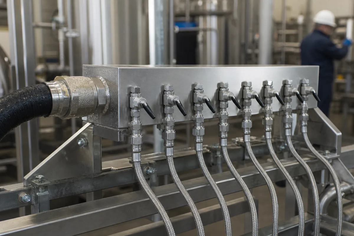
Representative product image. Confirm appearance and specifications with the manufacturer.

Product Specifications

Technical details and manufacturing context for Gas Inlet Manifold

Definition
The Gas Inlet Manifold is a critical component of a Gas Purging Station, serving as the primary entry and distribution point for the purge gas. It receives gas from the main supply line and evenly distributes it to multiple outlet ports, ensuring consistent flow and pressure to various sections or tools within the purging system. Its design is crucial for maintaining system efficiency and safety during purging operations. The manifold is typically constructed from materials such as stainless steel (e.g., 304, 316), carbon steel, or brass, depending on the application requirements. Key parameters include an operating pressure range of 1.0–1.6 MPa (with a note that), inlet connection sizes from DN50 to DN200 (flange type per customer request, per DIN EN 1092-1), and a customizable number of outlets ranging from 2 to 8. Outlet connection sizes range from DN15 to DN80, with threaded or flanged options per DIN EN 1092-1. Flow capacity is 100–1000 Nm³/h based on air at 1.0 MPa inlet. Material options include 316L (optional 304 or duplex) per ASTM A240. Surface finish can be electropolished to Ra ≤ 0.8 μm per ISO 4287 for clean gas applications. Operating temperature range is -40–85°C for non-freezing media. Leakage rate is ≤ 0.1 mL/min at 1.1 × rated pressure. Weight ranges from 15–120 kg depending on size and outlets. These values are reference ranges and must be verified for the specific model and application with the legal manufacturer or supplier. The manifold's design ensures balanced pressure distribution and minimizes pressure drops across the system, contributing to efficient and safe purging operations.
Working Principle
The manifold operates by receiving pressurized gas through a single inlet port. Internal channels or chambers within the manifold body divide and direct the gas flow to multiple outlet ports. Valves or regulators may be integrated to control the flow to individual outlets. The design ensures balanced pressure distribution and minimizes pressure drops across the system. The operating pressure range is 1.0–1.6 MPa, with a note that The number of outlets can be customized from 2 to 8, and outlet connection sizes range from DN15 to DN80 with threaded or flanged options. Flow capacity is 100–1000 Nm³/h based on air at 1.0 MPa inlet. The manifold is available in materials such as 316L (optional 304 or duplex) per ASTM A240, and surface finish can be electropolished to Ra ≤ 0.8 μm per ISO 4287. Operating temperature range is -40–85°C for non-freezing media. Leakage rate is ≤ 0.1 mL/min at 1.1 × rated pressure. These parameters are reference ranges and must be confirmed for the specific application.
Common Materials
Stainless Steel (e.g., 304, 316), Carbon Steel, Brass
Technical Parameters
ParameterTypical rangeNotes & selection driver
Operating Pressure1.0–1.6 MPa
Inlet Connection SizeDN50–DN200 mmFlange type per customer requestDIN EN 1092-1
Number of Outlets2–8Customizable manifold configuration
Outlet Connection SizeDN15–DN80 mmThreaded or flanged optionsDIN EN 1092-1
Flow Capacity100–1000 Nm³/hBased on air at 1.0 MPa inlet
Material316LOptional 304 or duplexASTM A240
Surface FinishRa ≤ 0.8 μmElectropolished for clean gasISO 4287
Operating Temperature-40–85 °CNon-freezing media
Leakage Rate≤ 0.1 mL/minAt 1.1 × rated pressure
Weight15–120 kgDepends on size and outlets

Ranges are indicative industry figures for RFQ preparation, not a supplier commitment. Confirm every value and standard with the legal manufacturer before ordering.

Components / BOM
  • Manifold Body
    The main structural block containing internal flow channels that distribute the gas.
    Material: Stainless Steel
  • Inlet Port Fitting Part
    Connection point for the main gas supply line to enter the manifold.
    Material: Brass or Steel
  • Outlet Port Fittings
    Multiple connection points where gas is distributed to downstream lines or tools.
    Material: Brass or Steel
  • Pressure Gauge Port (Optional) Optional Part
    A dedicated port for installing a pressure gauge to monitor inlet pressure.
    Material: Steel

Applied To / Applications

This component is essential for the following industrial systems and equipment:

Industrial Ecosystem & Supply Chain Structure

Complementary Systems
Downstream Applications
Specialized Tooling

Application Fit & Sizing Matrix

Operational Limits
pressure: Up to 300 psi (20.7 bar)
flow rate: 0.5 to 500 SCFM
temperature: -40°C to 150°C
slurry concentration: Not applicable - designed for clean gas only
Media Compatibility
✓ Natural gas distribution ✓ Industrial nitrogen purging ✓ Compressed air systems
Unsuitable: Corrosive gases (e.g., chlorine, hydrogen sulfide) without special coatings
Sizing Data Required
  • Maximum system pressure (psi/bar)
  • Total required flow rate (SCFM/Nm³/h)
  • Number of outlet connections required

Reliability & Engineering Risk Analysis

Failure Mode & Root Cause
Corrosion fatigue cracking
Cause: Cyclic thermal and pressure stresses combined with corrosive gas components (e.g., H2S, CO2, moisture) leading to crack initiation and propagation at stress concentration points like welds or bends.
Erosion-corrosion
Cause: High-velocity particulate-laden gas flow causing mechanical wear (erosion) that removes protective oxide layers, accelerating chemical attack (corrosion) on internal surfaces, especially at directional changes.
Maintenance Indicators
  • Audible high-frequency whistling or hissing indicating gas leakage through cracks or compromised seals
  • Visual external discoloration (e.g., blueing or rust streaks) at welds or fittings suggesting internal corrosion or overheating
Engineering Tips
  • Implement regular ultrasonic thickness testing and phased array ultrasonic testing at high-stress areas to monitor wall thinning and crack development before failure occurs.
  • Install properly sized inlet filters/separators and consider internal coatings (e.g., thermally sprayed aluminum or ceramic) to protect against erosion-corrosion in high-velocity sections.

Indicative industry ranges for design and RFQ preparation. Confirm the exact figures and applicable standard with the manufacturer before specifying.

Compliance & Manufacturing Standards

Applicable Standards
ISO 15649:2001 (Petroleum and natural gas industries - Piping) ASME B31.3:2022 (Process Piping)

Quoted from the published standard.

Manufacturing Precision
  • Bore diameter: +/-0.05mm
  • Flange flatness: 0.1mm per 300mm diameter
Quality Inspection
  • Hydrostatic pressure test (1.5x design pressure)
  • Dye penetrant inspection (weld seams and critical joints)

Manufacturers of Gas Inlet Manifold

Manufacturer profiles associated with Gas Inlet Manifold.

Sourcing Gas Inlet Manifold from China?
Tell us your specification and target quantity — we will match it against manufacturer records and come back with the factories that fit.
Request manufacturers We manufacture this

Manufacturer listings support early research and capability understanding. They are not certification, ranking, or transaction guarantees.

Technical documentation
Request current drawings, revision history, and a signed specification sheet.
Manufacturing capability
Verify equipment lists, process limits, capacity, and representative production evidence.
Inspection readiness
Confirm test methods, calibrated equipment, sampling plans, and traceable reports.
Supplier transparency
Check the legal entity, factory address, ownership, certifications, and direct contacts.

CNFX does not score or rank suppliers. Buyers must verify all claims and documents with the legal manufacturer before ordering.

Supply Chain Compatible Machinery & Devices

Automated Powder Coating System

Integrated industrial system for applying dry powder coatings to metal substrates.

Explore Specs →
Centrifugal Pump Impeller

The centrifugal pump impeller is a critical rotating component that converts mechanical energy from the motor into kinetic energy in fluid systems.

Explore Specs →
High-Precision CNC Laser Cutting Machine

Computer-controlled industrial machine using focused laser beams to cut sheet metal with micron-level accuracy.

Explore Specs →
Industrial-Grade Hydraulic Cylinder Piston Rod

This industrial-grade piston rod is a precision-ground cylindrical component designed for use in hydraulic cylinders.

Explore Specs →

Frequently Asked Questions

What is the operating pressure range for this manifold?

The reference operating pressure range is 1.0–1.6 MPa. Always verify the exact pressure rating for your specific model with the manufacturer.

How many outlets can the manifold have?

The number of outlets is customizable from 2 to 8, depending on the manifold configuration. Confirm the required number of outlets with the supplier for your application.

What materials are available for the manifold?

Materials on file include stainless steel (e.g., 304, 316), carbon steel, and brass. Additionally, a material option of 316L is listed, with optional 304 or duplex, per ASTM A240. Verify material suitability for your process conditions.

What is the leakage rate specification?

The leakage rate is ≤ 0.1 mL/min at 1.1 × rated pressure. This is a reference value; confirm the leakage performance for your specific manifold model.

Data Basis

Editorial classification, named public sources where available, and source-reviewed manufacturer records.

Preliminary Technical Classification
This page supports structured research, RFQ preparation, and supplier evaluation. It does not replace buyer-led supplier qualification, standards review, or technical approval.
Buyer enquiry

Request manufacturing insight for Gas Inlet Manifold

Ask for use case, specification boundaries, supplier type, and RFQ preparation information for this product.

Where it goes
Straight to the CNFX editorial desk, and to the manufacturer if this product is linked to a claimed profile. Nothing is broadcast to a supplier list.
Your details stay here
We do not sell or rent enquiry data, and we do not add you to a mailing list. Used only to answer this request.
No commission, no middleman
CNFX is a directory. We take no cut of any order and never negotiate on a supplier's behalf.
What we don't claim
A listing is not an endorsement. Qualify every supplier and verify every figure yourself before ordering.

Your business information is used only to process this request.

Thank you! Your message has been sent. We'll respond within 1–3 business days.
Sorry, we couldn't send your message. Please try again, or email us at contact@cnfx.com.

Need to Manufacture Gas Inlet Manifold?

Compare manufacturer profiles with relevant product and process capability.

Previous Product
Z-axis Ram/Spindle
Last Product
Get QuotesChat