Editorial Technical Reference

Gearbox

This page explains how Gearbox is classified within Machinery and Equipment Manufacturing. Technical values and manufacturer relationships are research references; confirm the current specification and supplier evidence for each order.

Technical Definition & Core Assembly

A mechanical device that transmits and modifies torque and speed from a power source to driven equipment.
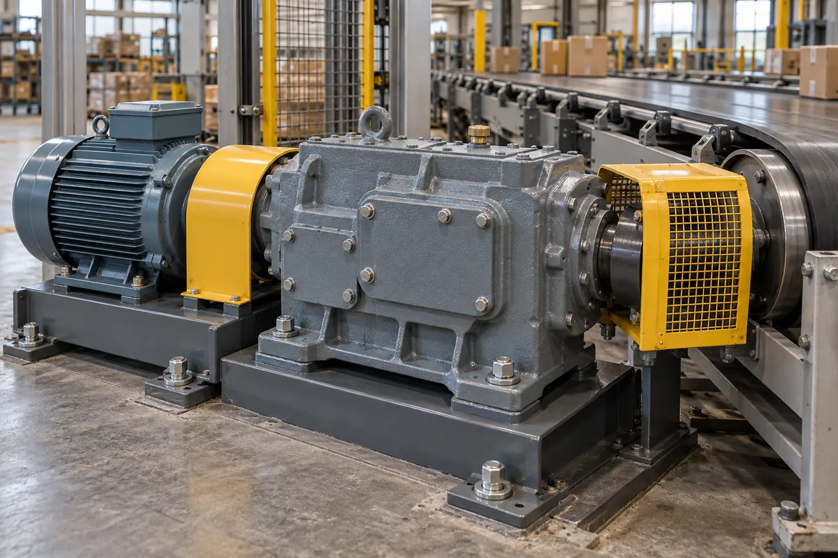
Representative product image. Confirm appearance and specifications with the manufacturer.

Product Specifications

Technical details and manufacturing context for Gearbox

Definition
A gearbox is a critical component within a drive system that uses gears and gear trains to provide speed and torque conversions from a rotating power source to another device. It serves as the interface between the prime mover (engine, motor) and the driven machinery, enabling optimal performance through gear ratio adjustments. Gearboxes are widely used in machinery and equipment manufacturing, where they adapt the output of electric motors or internal combustion engines to the requirements of industrial applications such as conveyors, pumps, and machine tools. The gearbox housing is typically made of cast iron, steel alloys, or aluminum alloys, and the gears are often case-hardened steel. Standard gearboxes cover a rated power range of 0.12–315 kW, with gear ratios from 1.25 to 450, output torque up to 50,000 N·m, and input speeds typically between 750 and 3000 rpm. Efficiency per stage is typically 94–98%, and the service factor should be selected based on load conditions, usually between 1.0 and 2.0. Noise levels at 1 m distance under no load are in the range of 60–85 dB(A), and operating temperature depends on lubricant, typically -20 to 80 °C. Protection classes range from IP54 to IP65, suitable for dusty or wet environments. Housing materials may be HT250 to QT450 cast iron or ductile iron, and gear materials include 20CrMnTi to 17CrNiMo6 case-hardened steels. Weight varies from 10 to 5000 kg depending on size and ratio. These values are reference ranges and must be verified for the specific model and application. Always confirm model-specific values and standards with the legal manufacturer or supplier before procurement.
Working Principle
The gearbox operates on the principle of mechanical advantage through gear ratios. Input torque from the power source rotates the input shaft, which engages with gears of different sizes. These gears transfer motion to the output shaft, either increasing torque while reducing speed (reduction gearbox) or increasing speed while reducing torque (overdrive gearbox), depending on the gear arrangement and ratios. The gear mesh transmits power while modifying the rotational speed and torque according to the ratio of the gear teeth. Lubrication is essential to reduce friction and heat, and the housing protects the gears from contamination. The selection of a gearbox requires consideration of input speed, required output torque, duty cycle, and environmental conditions.
Common Materials
Cast Iron, Steel Alloys, Aluminum Alloys
Technical Parameters
ParameterTypical rangeNotes & selection driver
Rated Power0.12–315 kWPower range for standard gearboxesISO 6336
Gear Ratio1.25–450Single or multi-stage reduction
Output Torque50–50000 N·mMaximum allowable torque at output shaftISO 6336
Input Speed750–3000 rpmTypical motor speed range
Efficiency94–98 %Per stage; lower for worm gearsISO 6336
Service Factor1.0–2.0Select based on load conditionsISO 6336
Noise Level60–85 dB(A)At 1 m distance, no loadISO 8579-1
Operating Temperature-20–80 °CLubricant dependentISO 6743-6
Protection ClassIP54–IP65Higher IP for dusty/wet environmentsIEC 60529
Housing MaterialHT250–QT450Cast iron or ductile ironGB/T 1348
Gear Material20CrMnTi–17CrNiMo6Case-hardened steelGB/T 3077
Weight10–5000 kgDepends on size and ratio

Ranges are indicative industry figures for RFQ preparation, not a supplier commitment. Confirm every value and standard with the legal manufacturer before ordering.

Components / BOM
  • Gears Part
    Transmit motion and torque between shafts through meshing teeth
    Material: Steel Alloy
  • Housing/Casing Part
    Encloses and protects internal components, provides structural support and lubrication containment
    Material: Cast Iron or Aluminum
  • Input Shaft Part
    Receives rotational power from the prime mover and transfers it to the gear train
    Material: Steel Alloy
  • Output Shaft Part
    Delivers modified torque and speed to the driven equipment
    Material: Steel Alloy
  • Bearings
    Support rotating shafts and reduce friction between moving parts
    Material: Steel with special coatings

Applied To / Applications

This component is essential for the following industrial systems and equipment:

Industrial Ecosystem & Supply Chain Structure

Complementary Systems
Downstream Applications
Specialized Tooling

Application Fit & Sizing Matrix

Operational Limits
pressure: Atmospheric to 10 bar (standard housing), higher with pressurized lubrication systems
efficiency: 94-98% (helical gears), 85-92% (worm gears)
speed range: Input: 500-3600 RPM, Output: 10-1800 RPM (typical)
temperature: -20°C to 120°C (standard), up to 150°C with special seals/lubricants
torque capacity: Up to 50,000 Nm (varies by size and gear ratio)
Media Compatibility
✓ Industrial lubricating oils (ISO VG 68-320) ✓ Synthetic gear lubricants ✓ Food-grade lubricants (USDA H1)
Unsuitable: High-concentration abrasive slurries or corrosive chemical environments without special protection
Sizing Data Required
  • Required output torque (Nm or lb-ft)
  • Input speed (RPM) and desired output speed (RPM)
  • Service factor (based on duty cycle and load characteristics)

Reliability & Engineering Risk Analysis

Failure Mode & Root Cause
Tooth pitting and spalling
Cause: Surface fatigue due to cyclic contact stress exceeding material endurance limit, often accelerated by inadequate lubrication, misalignment, or overloading.
Bearing failure
Cause: Premature wear or seizure from contamination (debris, moisture), improper lubrication (wrong type, insufficient quantity), or excessive axial/radial loads beyond design specifications.
Maintenance Indicators
  • Unusual high-frequency whining or grinding noises during operation
  • Visible oil leaks around seals or housing, especially with metallic particles in leaked fluid
Engineering Tips
  • Implement condition-based monitoring with vibration analysis and oil analysis to detect early wear patterns and lubricant degradation
  • Ensure precise alignment during installation and maintain proper lubrication with filtered, clean oil at correct viscosity and temperature ranges

Indicative industry ranges for design and RFQ preparation. Confirm the exact figures and applicable standard with the manufacturer before specifying.

Compliance & Manufacturing Standards

Applicable Standards
ISO 1328-1:2013 Cylindrical gears - ISO system of flank tolerance classification ANSI/AGMA 2000-A88 Gear Classification and Inspection Handbook DIN 3961 Tolerances for cylindrical gear teeth

Quoted from the published standard.

Manufacturing Precision
  • Tooth profile deviation: ±0.005 mm
  • Center distance tolerance: ±0.02 mm
Quality Inspection
  • Gear tooth contact pattern test
  • Hardness testing (Rockwell C scale)

Manufacturers of Gearbox

Manufacturer profiles associated with Gearbox.

Sourcing Gearbox from China?
Tell us your specification and target quantity — we will match it against manufacturer records and come back with the factories that fit.
Request manufacturers We manufacture this

Manufacturer listings support early research and capability understanding. They are not certification, ranking, or transaction guarantees.

Technical documentation
Request current drawings, revision history, and a signed specification sheet.
Manufacturing capability
Verify equipment lists, process limits, capacity, and representative production evidence.
Inspection readiness
Confirm test methods, calibrated equipment, sampling plans, and traceable reports.
Supplier transparency
Check the legal entity, factory address, ownership, certifications, and direct contacts.

CNFX does not score or rank suppliers. Buyers must verify all claims and documents with the legal manufacturer before ordering.

Supply Chain Compatible Machinery & Devices

Heavy-Duty CNC Plasma Cutting Machine

The Heavy-Duty CNC Plasma Cutting Machine is a standalone industrial device designed for cutting conductive metals such as steel, stainless steel, aluminum, and copper alloys.

Explore Specs →
Automated Powder Coating System

Integrated industrial system for applying dry powder coatings to metal substrates.

Explore Specs →
Centrifugal Pump Impeller

The centrifugal pump impeller is a critical rotating component that converts mechanical energy from the motor into kinetic energy in fluid systems.

Explore Specs →
High-Precision CNC Laser Cutting Machine

Computer-controlled industrial machine using focused laser beams to cut sheet metal with micron-level accuracy.

Explore Specs →

Frequently Asked Questions

What is the typical power range for a standard gearbox?

Standard gearboxes typically cover a rated power range of 0.12 to 315 kW, as per ISO 6336. However, the exact power rating depends on the specific model and application, so always verify with the manufacturer.

What gear ratios are available?

Gear ratios for standard gearboxes range from 1.25 to 450, allowing for single or multi-stage reduction. The required ratio depends on the desired output speed and torque for your application.

What materials are commonly used for gearbox housings and gears?

Housings are often made of cast iron (e.g., HT250) or ductile iron (e.g., QT450), while gears are typically case-hardened steel such as 20CrMnTi or 17CrNiMo6. These materials provide strength and wear resistance.

How do I select the right gearbox for my application?

Selection involves determining the required output torque, input speed, gear ratio, service factor, and environmental conditions. Reference values like those listed (e.g., power, torque, efficiency) are starting points; always consult the manufacturer for model-specific data.

Data Basis

Editorial classification, named public sources where available, and source-reviewed manufacturer records.

Preliminary Technical Classification
This page supports structured research, RFQ preparation, and supplier evaluation. It does not replace buyer-led supplier qualification, standards review, or technical approval.
Buyer enquiry

Request manufacturing insight for Gearbox

Ask for use case, specification boundaries, supplier type, and RFQ preparation information for this product.

Where it goes
Straight to the CNFX editorial desk, and to the manufacturer if this product is linked to a claimed profile. Nothing is broadcast to a supplier list.
Your details stay here
We do not sell or rent enquiry data, and we do not add you to a mailing list. Used only to answer this request.
No commission, no middleman
CNFX is a directory. We take no cut of any order and never negotiate on a supplier's behalf.
What we don't claim
A listing is not an endorsement. Qualify every supplier and verify every figure yourself before ordering.

Your business information is used only to process this request.

Thank you! Your message has been sent. We'll respond within 1–3 business days.
Sorry, we couldn't send your message. Please try again, or email us at contact@cnfx.com.

Need to Manufacture Gearbox?

Compare manufacturer profiles with relevant product and process capability.

Previous Product
Gear Train (Spur/Helical/Planetary)
Next Product
Gearbox (if applicable)
Get QuotesChat