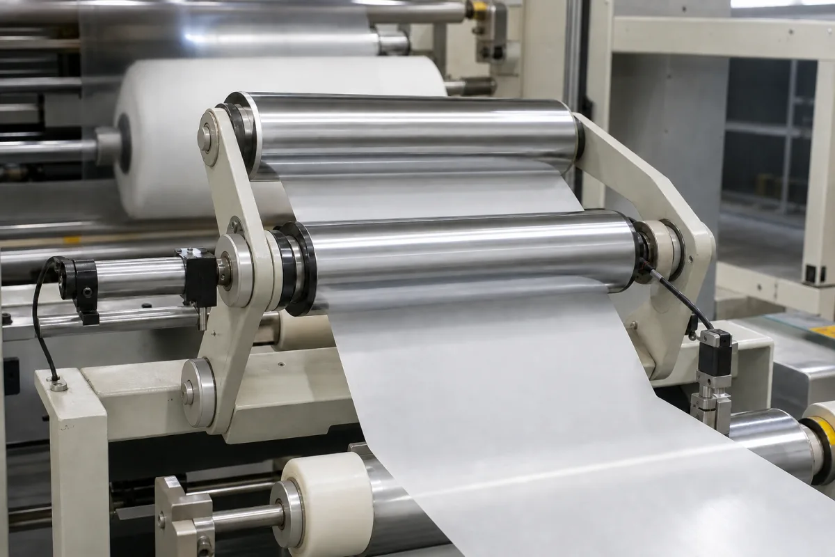
Guiding roller assembly for wide webs: the pivoting two-roll frame or roller basket of an intermediate web guide, rated by roll length, span, diameter, correction travel and speed, and web tension
The pivoting roll frame that physically moves a wide web sideways · roll length and span, roll diameter and material, how far and how fast the frame corrects, and how much web tension it carries
In an intermediate web guide the sensor and controller decide where the web should be, but a frame of rollers does the moving: it pivots about a point upstream so the web leaves it displaced sideways, without twisting the web more than it must. For wide webs that frame is a substantial machine in its own right, bought by roll length, the distance between its rolls, roll diameter and material, how far and how fast it can correct, and the web tension its rolls and pivot supports can carry. The figures below compare three frames for webs from 500 mm to 3 m.
Pivoting roll frames (two-roll offset pivot frames and multi-roll roller baskets) of intermediate web guides for wide webs, with their rolls, pivot supports, guideways, drives and mounting: roll length, span and diameter, roll material, correction travel and speed, positional accuracy and web tension rating. Complete web guiding systems, guide type selection, span sizing and sensors are covered on the Web edge guide system page; compact guides for narrow label and converting webs on the Narrow-web guiding system page. Unwind and rewind guides that shift the whole roll stand are outside this page.
CNFX editorial research · Sources checked October 13, 2026 · 3 sources
Three wide-web roll frames side by side: rolls to 3000 mm, spans to 1300 mm, tension ratings from 1176 to 2504
Each maker states the frame's size and load differently; the table keeps their own terms.
Editorial calculation: per millimetre of web width at the top of each range, Erhardt+Leimer's 2000 N over 700 mm is 2.9 N/mm and Fife's 2504 N over 1930 mm is 1.3 N/mm; Mitsuhashi's 1176 over 3000 mm would be 0.39 N/mm if the unstated unit is newtons. [2][3][1] A line running heavier tension on a wide web is therefore inside one frame's rating and outside another's, which is why the tension at the guide position belongs in the enquiry beside the width.
Mitsuhashi's drawing for the PGM-400 names the parts a buyer is pricing: roll stands, roll frame, drive, front-side roll, end-side roll and electrical box, and defines the roll surface length, the distance between roll outer diameters and the roll centre distance that set the frame's size. [1]
Frame
Web or roll size
Rolls
Web tension rating
Construction stated
Mitsuhashi PGM-400 large roll guide (offset type)
Roll surface length 400–3000 mm; roll span 300–1300 mm; webs of 3000 mm or less
Ø100 mm standard, Ø75–160 mm possible; aluminium, iron, rubber and others
Maximum web tension 1176 (unit not stated on the page)
Ball screw drive with minimal backlash; roll support reworked so the support point carries 4 times the load of Mitsuhashi's earlier guide [1]
Erhardt+Leimer ELGUIDER DRB73 roller basket
Nominal width 500–700 mm; transfer length 1300 mm
2 × 168 mm and 5 × 84 mm
Max. 2000 N
Pivoting frame with brushless digital drive; IP 54 [2]
Fife LRB offset pivot guide
Webs up to 76.0 in (1930 mm)
Construction and roller options to order
Up to 563 lbf (2504 N)
Low-friction ball bushings on precision race-rod supports; electromechanical actuator or hydraulic cylinder; Type 40 (inside the framework) or Type 50 (on top) mounting base [3]
Give the web width and the roll surface length needed, the web tension at the guide position, the roll diameter and covering wanted, the space available for the span between rolls, and whether the frame mounts inside or on top of the machine frame.
02
How far and how fast the frame corrects: ±25 mm at 1 to 30 mm/s on a roller basket, 25 mm/s on a ball-screw roll guide
Erhardt+Leimer gives the DRB73's nominal actuating travel as max. ±25 mm across transfer lengths from 600 to 2500 mm, and its nominal actuating speed at the outfeed roller as 1 to 30 mm/s (stated with its AG 93 actuator at F = 3000 N), with positional accuracy better than ±0.2 mm. [2] Mitsuhashi gives the PGM-400 a driving speed of 25 mm/s from a 24 V DC supply drawing at most 2.5 A. [1]
Editorial calculation: a full ±25 mm correction takes 25 / 30 = 0.83 s at the DRB73's top speed and 1.0 s at the PGM-400's 25 mm/s. [2][1] The frame's speed is a limit on how fast a drift it can follow, not on accuracy, which Erhardt+Leimer states separately as better than ±0.2 mm. [2]
Fife's LRB offers the actuator choice instead: an electromechanical actuator or a hydraulic cylinder, with an optional Servo-Center to bring the frame to centre for threading, and accepts its range of edge, line and centre sensors. [3] Erhardt+Leimer's DRB73 pairs with an infrared wide-band sensor or a CCD camera and has an Ethernet UDP/IP or EtherNet/IP interface, operating between +10 and +50 °C at 15–95 % relative humidity without condensation. [2]
The image above shows a frame of this kind on a film line: two polished rolls carried in pivoting side plates, the white film wrapping them, with sensors mounted on brackets at the frame's sides.
State the line speed, the largest lateral drift expected, the correction travel and positional accuracy required, the actuator type and supply (24 V DC, hydraulic), and the controller interface.
03
Roll frame details to send
Paste it into your enquiry below or into an email to a maker, then replace every bracket.
Web: [material; width; tension at the guide]
Rolls: [surface length; diameter; material or covering; span between rolls]
Correction: [travel ±mm; speed mm/s; accuracy]
Drive: [electromechanical; hydraulic; supply]
Mounting: [inside or on top of the frame; space available]
Controls: [sensor type; controller; fieldbus]
Explore company information and manufacturing capabilities, then discuss the scope of your project with a relevant supplier.
Share this page
Compiled and source-reviewed by the CNFX editorial team.
Each manufacturer above links to the page on that company's own website where the product is listed, with the date we checked it. How we source and review
· Page last updated 13 October 2026
Buyer questions
How long can the rolls of a web guide roll frame be?
Mitsuhashi lists roll surface lengths of 400 to 3000 mm for its PGM-400 large roll guide, on roll spans of 300 to 1300 mm with Ø100 mm standard rolls. [1]
How much web tension can a guide roll frame carry?
Erhardt+Leimer rates its DRB73 roller basket at a maximum of 2000 N and Fife rates its LRB offset pivot guide at up to 563 lbf (2504 N) for webs up to 1930 mm. [2][3]
How fast does a wide-web guide frame correct?
Erhardt+Leimer gives the DRB73 1 to 30 mm/s at the outfeed roller over a ±25 mm travel; Mitsuhashi gives 25 mm/s for the PGM-400. [2][1]
Sources and what still needs a direct check
Sources checked 2026-10-13. Three sources from three publishers: Mitsuhashi's PGM-400 large roll guide specification page, Erhardt+Leimer's ELGUIDER DRB73 roller basket technical data, and Maxcess's Fife LRB offset pivot guide product sheet.