Boiler and HRSG headers that have to survive starts and stops
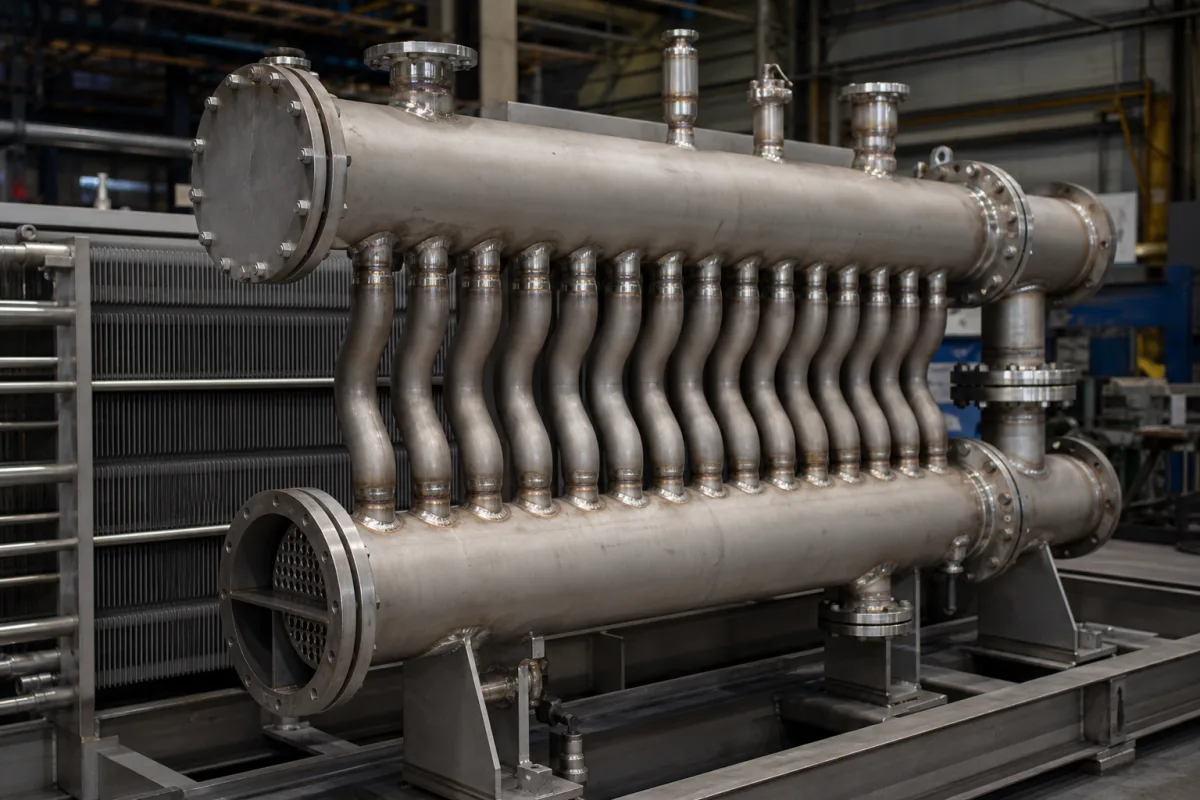
The illustrated assembly is a pair of thick-walled headers joined by a row of bent connecting tubes, standing beside a finned tube bank. In a boiler or heat recovery steam generator (HRSG), headers like these distribute steam or water into parallel tubes and collect it again, and in hot sections they carry the highest stresses in the circuit. Three POWER magazine articles and a failure analysis published by IntechOpen describe where such headers and their tube connections fail.
Covers tube headers and manifolds in boilers and HRSGs: superheater and reheater inlet and outlet headers, the stub tubes and link pipes joining them to tube rows, header supports and flexibility, ligament cracking between tube bores, and their inspection. The original catalogue definition described heat-exchanger headers and manifolds without naming a service; plate heat exchangers are on 599, finned-tube cores on 3727, economizers on 9102. Steam distribution headers for process steam are on 2977 and 3323, steam tracing manifolds on 3108, hydraulic manifold blocks on 5438 and 7963.
CNFX editorial research · Sources checked October 13, 2026 · 4 sources
Writing in POWER in 2006 with figures from Nooter/Eriksen, the authors of "Designing HRSGs for cycling" state that in HRSGs low-cycle fatigue is almost always due to unresolved thermal expansion, and that EN 12952 and TRD 301 give rules for high-cycle fatigue but none for low-cycle creep and fatigue.
The article places the row-to-row temperature and expansion differences at their greatest during unit start-up, narrowing as full steam flow is established. It adds that interconnecting pipes not heated by gas flow can run hundreds of degrees Fahrenheit cooler than the superheater and reheater coils they join during start-up, so that piping needs its own flexibility.
The bent connecting tubes in the illustration are the kind of flexibility the article argues for: each bend lets one header move relative to the other without loading the tube-to-header welds (editorial reading of the image).
Arrangement (POWER 2006)
What happens on start-up
One upper header fixed, the other spring-supported, lower headers free to move vertically
The spring lets that tube row move vertically, reducing thermally induced stress by an order of magnitude
Both upper headers restrained from moving vertically
Row-to-row temperature differences must be absorbed by header rotation, tube flexing or axial load in the tubes; the unit is damaged slightly each time it cycles
Each row hung from its own fixed upper header, lower headers joined to a collector manifold by link pipes
Absorption depends entirely on the flexibility of coils and link pipes and rotation of the manifold; maximum thermal stress sits at the bends in the link pipes
Tube rows tied together by upper and lower headers or a manifold
Works in evaporators, where row-to-row differences are very small, but leaves superheater and reheater tubes open to cycling fatigue
These are design arguments from one HRSG maker's engineers; the stress reduction is their figure for the arrangement shown in their figure 1.
02
Stub tubes at the header ends: where differential expansion bends hardest
David N. French Metallurgists, writing in POWER in 2018, describe creep fatigue at the stub-tube-to-header welds toward the ends of high-temperature superheater and reheater outlet headers, and simple thermal fatigue at the same places on headers below the creep range.
With those inputs, the header grows about 0.0031 in per inch more than the roof, about 3.1 mm per metre measured from the header midpoint; a stub tube 3 m from the midpoint has to absorb about 9.4 mm of sideways movement (Editorial calculation).
An HRSG case published by Mokhtar and Kamarul Bahrin of Universiti Teknologi PETRONAS points the same way. After about 85,000 hours, and after the plant moved from base load to cyclic operation in its seventh year, 17 connecting tubes of a high-pressure superheater outlet header failed, all next to each other in one row. They attributed the failures to long-term creep and thermal fatigue from daily start-stop, measured heat-affected-zone hardness down to 142 HV against an acceptable 200–260 HV on the T91 tubes, and found a damaged flow correcting device whose flow imbalance accelerated creep.
Point
Source
Differential expansion between the hotter header and cooler waterwalls deflects the stub tubes between them; the deflection is greatest at the header ends
POWER 2018
Stress from that deflection falls as the stub tube gets longer and rises with longer headers, larger header-to-waterwall temperature difference and larger stub diameter
POWER 2018 (beam-theory estimate)
Worked inputs: outlet header at 1,000 °F, waterwall roof at 650 °F; expansion coefficient 7.97 × 10⁻⁶ /°F for T22 and 7.35 × 10⁻⁶ /°F for SA-210 A1
POWER 2018
First thorough inspection belongs at the end tubes with the shortest length
POWER 2018
Case: 33-year-old boiler, cracks at the inner tubes of an eight-tube array, on the tube wall facing the header end, at a dissimilar-metal weld between 2.25 in T22 and 1.75 in TP321H tubes
POWER 2018
The 3 m example distance is an editorial assumption to show scale, not a figure from the article.
03
Ligaments between tube bores, and the girth welds they cross
A 2007 POWER article built on Thielsch Engineering case files explains that in superheater and reheater outlet headers with multiple radial tube bores, the ligaments between adjacent bores carry the highest stresses of any part of the header body, because each hole reduces the load-bearing cross-section.
The article's recommended full inspection starts with magnetic particle examination of every weld on the header, including header-to-tube stub welds, then volumetric examination of butt welds, a borescope look at the inside, and in-situ replication and hardness testing. Where budget or outage time is short, it suggests limiting the work to headers prone to deterioration and to areas where tube holes overlap a girth weld.
In one of its cases a header leaked after 28 years at a place where tube holes overlapped a counterbored girth weld with low-carbon filler; none of the other 250 header-to-tube stub welds showed cracking. The authors put repair of a failed header at weeks and replacement at up to six months.
What weakens the header (POWER 2007)
Effect
Wall thickness at or barely above code minimum
Less margin for stresses not anticipated: bending from malfunctioning supports, rushed start-ups, cycling of units not designed for it
Counterboring the inside diameter at circumferential butt welds
Removes about 1/4 to 3/8 in of wall at the joint
Flat-topping girth welds
May remove too much material and reduce joint strength
Creep strength 20% to 30% lower than standard Cr-Mo electrodes in certain regions
A row of tube holes overlapping or bisecting a circumferential butt weld
Field reports of severe ligament cracking at these spots
04
What to give a header fabricator
Paste it into your enquiry below or into an email to a maker, then replace every bracket.
Give the service (superheater, reheater, evaporator, economizer), design pressure and temperature, header and tube materials and sizes, tube-hole pattern and number of rows, the planned number of starts and the start-up rate, and how the header is supported. Ask for the header wall thickness against the code minimum, ligament efficiency at the tube holes, position of circumferential welds relative to tube holes, weld procedure and filler for girth and stub welds, dissimilar-metal weld details, support and flexibility arrangement, and the NDE and hardness records.
1 company lists this product among what they make. Company figures are quoted from each
company's own website; every card states where the relationship came from.
Suzhou Orl Power Engineering Co., Ltd.
card
Lists boiler headers among its boiler pressure parts. Location TBC.
Explore company information and manufacturing capabilities, then discuss the scope of your project with a relevant supplier.
Share this page
Compiled and source-reviewed by the CNFX editorial team.
Each manufacturer above links to the page on that company's own website where the product is listed, with the date we checked it. How we source and review
· Page last updated 13 October 2026
Buyer questions
Why do HRSG headers crack when a plant starts cycling?
POWER's 2006 article on HRSG design attributes low-cycle fatigue in HRSGs to unresolved thermal expansion between tube rows and headers, highest during start-up and shutdown. [2]
Which stub tubes on a header should be inspected first?
David N. French Metallurgists (POWER 2018) point to the end tubes with the shortest length, where the deflection from differential expansion between header and waterwall is greatest. [3]
What is ligament cracking in a boiler header?
Cracking in the metal between adjacent tube bores; POWER's 2007 article reports it where rows of tube holes overlap circumferential butt welds, linked to thin walls and creep damage. [1]
Does switching an HRSG from base load to cycling affect header tubes?
In a case analysed by Universiti Teknologi PETRONAS researchers, tube failures at a superheater outlet header increased after the plant moved to cyclic operation; they found long-term creep and thermal fatigue from daily start-stop. [4]
Sources and what still needs a direct check
Sources checked 2026-10-13. Three POWER magazine articles on header cracking, boiler ageing and HRSG design for cycling, and a university failure analysis of an HRSG superheater outlet header published by IntechOpen.