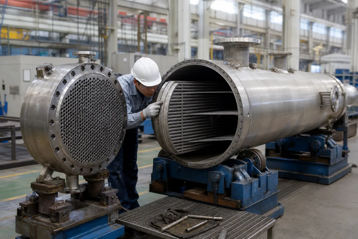
Process equipment · Moving heat without mixing fluids
A heat exchanger transfers heat between two fluids through a wall. Its size follows from the duty, the temperatures on both sides and the pressure drop you can afford. Two ways to waste money are an approach temperature tighter than needed and a fouling allowance copied from the wrong exchanger type.
Industrial heat exchangers: gasketed, brazed and welded plate units, shell-and-tube, spiral, finned-tube, air-oil coolers and air-to-air heat-recovery cores. Boilers, condensers with vacuum systems and cooling towers are separate purchases.
CNFX editorial research · Sources checked October 12, 2026 · 12 sources
Alfa Laval lists six parameters needed to solve a heat-exchanger problem: the heat load, the inlet and outlet temperatures on both sides, the maximum allowable pressure drop on both sides, the maximum operating temperature and pressure, and the flow rate on both sides. The heat load follows from P = m × cp × δt and must equal k × A × LMTD. [1]
LMTD, the logarithmic mean temperature difference, is (ΔT1 − ΔT2) ÷ ln(ΔT1 ÷ ΔT2), where ΔT1 is hot inlet minus cold outlet and ΔT2 is hot outlet minus cold inlet. For a fixed duty and heat-transfer coefficient, the area needed rises as LMTD falls. [1]
As a calculation example only, cooling 10 m³/h of water from 30 to 20 °C removes about 10,000 kg/h × 4.18 kJ/(kg·K) × 10 K ≈ 418,000 kJ/h, or 116 kW. If the cooling water enters at 15 °C and leaves at 25 °C, ΔT1 = 30 − 25 = 5 K and ΔT2 = 20 − 15 = 5 K, so LMTD = 5 K (when both end differences are equal, LMTD equals that difference). Use your own fluids, specific heats and temperatures.
Alfa Laval notes that area does not grow linearly as the approach tightens: the last few tenths of a degree are disproportionately expensive, and relaxing the approach by 0.1–0.2 °F can greatly reduce the size of a plate exchanger. Check whether your process really needs the closest approach requested. [2]
Send both sides' fluids, flows, inlet and outlet temperatures, allowable pressure drops and design pressure and temperature. An enquiry that gives only 'kW' or 'm²' cannot be sized or compared.
02
Choose the type from the fluids, pressure and cleaning
Suppliers linked to this page cover more than one distinct type. The right one depends on the two media, pressure and temperature, fouling and how the unit will be cleaned.
Type
Characteristics from the sources
Ask for
Gasketed plate (plate-and-frame)
Corrugated plates and narrow channels create turbulence and high wall shear; plates can be added to the frame to change duty. [3][4][5]
Plate material and thickness, gasket compound, frame extension capacity, opening for cleaning.
Brazed and welded plate
Compact plate packs without gaskets, offered by plate-exchanger makers alongside gasketed units. [4][5]
Pressure and temperature limits, brazing material, and whether the pack can be cleaned only chemically.
Shell-and-tube
Tube bundle inside a shell; tubes are also sold separately as heat-exchanger tubing. [4][11][12]
Tube material, size and wall, number of passes, baffles, and removable bundle for cleaning.
Finned-tube and air-cooled
Fins increase the air-side area; air-oil coolers are used on hydraulic systems. [6][7]
Fin type and spacing, air flow, fan power and noise, design ambient.
Air-to-air heat recovery
Crossflow, counter-flow, heat-pipe and rotary cores for ventilation. [8][9]
Effectiveness at rated air flow, leakage between streams, and frost control.
Titanium and corrosion-resistant units
Titanium heat exchangers for electrolysis and smelting service. [10]
Material grade and fabrication standard for the corrosive medium.
03
Set the fouling margin for the exchanger type
The Heat Exchange Institute defines fouling as the loss of heat transfer over time from deposits on the walls. Designers size with a fouled coefficient Uf rather than the clean value Uc, using a fouling factor (1/Uf = 1/Uc + ff), a fouling margin (Uf = Uc ÷ (1 + fm%)) or a cleanliness factor (Uf = Uc × cf). [3]
More margin is not always safer
HEI warns that excessive fouling factors or over-surfacing give an uneconomic design, poor control and more fouling, because velocities fall. It states that "the removal rate of fouling is primarily a function of the wall shear stresses", which are "directly proportional to the pressure drop". [3]
Alfa Laval shows why the same fouling factor gives very different margins: the design margin M = kc × Rf, so an exchanger with a high clean coefficient kc gets a much larger margin from the same Rf. [1]
Plate units need their own approach
HEI states that "PHE's can generate shear stresses generally five times higher than those generated in an equivalent shell and tube heat exchanger" and that TEMA fouling factors should not be used for plate designs. It describes power-plant practice of a 5–10% fouling margin with a frame able to take 30–50% more plates. [3]
For open HVAC systems Alfa Laval targets a wall shear stress of 50 Pa, with 35 Pa as a minimum, recommends a port filter with mesh about 75% of the channel gap, and limits the pressure drop lost in the connections to 30–35% of the total so flow reaches the whole plate pack. [2]
Plan for cleaning and redundancy
HEI notes that "plants often design with redundant heat exchangers" — "very often 100 % spare heat exchangers (2 x 100% parallel units) or 50% spares ( 3 x 50% parallel units)" — so one can be cleaned or repaired without stopping the process, and that a higher allowable pressure drop raises pumping cost but gives higher U values, lower fouling and a smaller unit. Compare these options on total cost. [3]
04
Trace the heat exchanger components
This is a functional reference built from the sources cited; it is not one maker's parts list. Components differ by type; materials and dimensions come from the data sheet of the unit you order.
Part
Role
Fix in the order
Heat-transfer plates
Corrugated plates form the channels in plate units; the corrugation angle (theta) changes turbulence and pressure drop. [2][3]
Plate material, thickness and pattern.
Heat-transfer tubes
Carry one fluid in shell-and-tube and finned units. [11][12][6]
Tube material, diameter, wall thickness and finning.
Gaskets and seals
Seal plate channels or tube-side covers; compound must suit both media and temperature. [4]
Gasket compound and fixing method (glued or clip-on).
Frame, shell and tubesheets
Hold the plate pack or tube bundle and contain pressure. [4]
Design pressure and temperature, construction code and material.
Headers, nozzles and ports
Distribute flow; excessive connection pressure drop starves the plate pack. [2]
Connection size and standard, and the pressure drop in the connections.
Port filters and strainers
Protect narrow channels from particles and plugging. [2][3]
Filter mesh relative to channel gap.
Fins and fans (air-cooled)
Extend the air-side surface and move the air. [6][7]
Fin pitch, fan type and power.
05
Fill the specification fields with values for your duty
A heat-exchanger quotation needs duty-specific values. The table explains each field, gives published values where a reviewed source states them, and says what to obtain from the supplier.
These companies make different types of heat exchanger or their key parts: plate and shell-and-tube units, finned and air-oil coolers, air-to-air recovery cores, titanium units, electronics cold plates and heat-exchanger tubing.
Guangdong Jiema Energy Saving Technology Co.,Ltd
Manufacturing site to be confirmed for the order
Lists plate-and-frame, brazed, welded, pillow-plate, shell-and-plate, spiral and shell-and-tube heat exchangers, plus replacement plates and gaskets.
Explore company information and manufacturing capabilities, then discuss the scope of your project with a relevant supplier.
Share this page
Compiled and source-reviewed by the CNFX editorial team.
Published product pages show what a company offers, not tested performance. Confirm the legal seller, factory and scope for your order. How we source and review
· Page last updated 13 October 2026
Buyer questions
Should I use the same fouling factor for a plate exchanger as for shell-and-tube?
No. HEI states that plate units "can generate shear stresses generally five times higher than those generated in an equivalent shell and tube heat exchanger" and that TEMA fouling factors should not be applied to plate designs, because they lead to excessive area. [3]
Why does a slightly tighter approach temperature cost so much?
Alfa Laval notes the relationship between approach and area is not linear: the last tenths of a degree are disproportionately expensive, and relaxing the approach by 0.1–0.2 °F can greatly reduce plate-exchanger size. [2]
How can I allow for future capacity in a plate exchanger?
HEI describes specifying a frame with 30–50% extension capacity so plates can be added later, alongside a nominal 5–10% fouling margin. [3]
Sources and what still needs a direct check
Sources checked 2026-10-12. Alfa Laval is a manufacturer and HEI a trade association of heat-exchanger manufacturers; their equations and recommendations are used with the context they give. Supplier pages describe their own offers. TEMA and pressure-vessel codes were not read for this page.