Condensing a mixture of vapours, not a single solvent
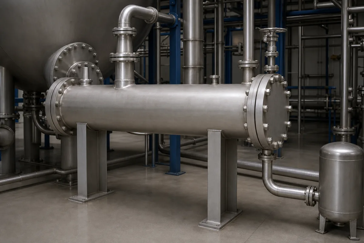
The condenser in the illustration is a horizontal shell-and-tube unit taking vapour in at the top of the shell and draining condensate from the bottom into a small receiver. If that vapour were one pure solvent it would condense at one temperature. In solvent recovery and distillation it rarely is: a mixture of components with different boiling points condenses over a range, the lighter ones last, and both the surface needed and what ends up in the receiver depend on how the design treats that range.
Covers condensers handling multicomponent vapour mixtures in chemical processing, solvent recovery and pyrolysis vapour recovery: condensation over a temperature range, sensible heat and mass-transfer resistance in the vapour, design methods (Kern, Bell–Ghaly, resistance proration, film theory), immiscible condensates, and staged condensers at controlled temperatures. Recovery duty, coolant temperature, area, icing and refrigerated vapour-recovery condensers are on Condenser (process and vapour recovery); refrigeration condensing units for air conditioners and refrigerators are outside this page.
CNFX editorial research · Sources checked October 13, 2026 · 3 sources
Bandyopadhyay and co-authors (Chemical and Biochemical Engineering Quarterly 21(2), 2007) define the problem: in multicomponent condensation the vapour contains components with different boiling points that condense over a wide temperature range, with or without non-condensing material.
As the mixture cools along the condenser, the heaviest components condense first and the vapour left behind becomes richer in the light ones, so the condensing temperature falls along the exchanger. Heat has to be removed not only as latent heat but also as sensible heat from the vapour, and the components have to diffuse through the vapour to the condensate film; both add resistance that a pure-vapour condenser does not have.
Their worked case was a hydrocarbon vapour of propane, butane, hexane, heptane and octane (mole fractions 0.15, 0.25, 0.05, 0.30 and 0.25) on the shell side of a vertical shell-and-tube condenser. They studied how vapour flow rate, coolant flow rate, vapour inlet temperature and coolant inlet temperature change the overall coefficient and shell-side pressure drop.
Component (Bandyopadhyay et al. example)
Mole fraction
Propane
0.15
Butane
0.25
Hexane
0.05
Heptane
0.30
Octane
0.25
The description of how vapour composition shifts along the condenser is an editorial explanation of the paper's starting point. Give the supplier the full vapour composition, not just the main solvent, including any non-condensable gas.
02
Which design method, and why it matters
Bandyopadhyay et al. coded both Kern's method and Bell and Ghaly's method for the same duty. Kern's method gave a smaller heat transfer area because it neither accounts for mass-transfer resistance nor handles the sensible heat removed during condensation; Bell and Ghaly's method includes them, using a single-phase coefficient for the vapour's sensible heat transfer. A condenser sized by the simpler method is therefore undersized for a mixture.
HTRI's report CG-7 (Sardesai, 1994) goes a step further. The resistance proration method, used for years, assumes condensation follows the equilibrium condensation curve; that assumption, by the report's account, fails for a good share of mixtures and can give significant errors for mixtures with a wide range of molecular weights. Film-theory methods such as Colburn–Hougen and Krishna–Standart were found accurate over a wide range of conditions. The report also covers vapours that condense to immiscible liquids, where mass transfer differs depending on whether the mixture is eutectic, and the extra complication of a non-condensing gas.
Method
Accounts for
Risk (per the sources)
Kern
Overall coefficient, no vapour mass transfer or sensible-heat handling
Too little area for mixtures (Bandyopadhyay et al.)
Bell–Ghaly / resistance proration
Sensible heat via a vapour-phase coefficient; equilibrium condensation curve
Errors for wide molecular-weight ranges (HTRI CG-7)
Film theory (Colburn–Hougen, Krishna–Standart)
Mass transfer through the vapour film
Recommended over a wide range of conditions (HTRI CG-7)
Ask which method the supplier's thermal design uses for the condensing zone, and whether the condensing curve was calculated or assumed.
03
Using temperature to split the condensate
Pannucharoenwong and co-authors (ACS Omega, 2026) condensed pyrolysis vapour from waste plastic bags in two condensers held at different temperatures.
Vapour from a 500 °C fixed-bed reactor passed a hot filter, a first refrigerated condenser at 50 °C with an electrostatic precipitator to remove aerosols and tar mist, and a second condenser set in turn to −10, −20, −30 and −40 °C. Lowering the second condenser from −10 to −40 °C raised the light liquid yield from 10.5% to 32.7% and cut the gas yield from 27.4% to 5.4%; benzene and toluene dominated the liquids collected at −40 and −30 °C, longer-chain compounds such as cyclononane those at −20 and −10 °C.
The same principle applies in a solvent-recovery train: a warmer first condenser takes the heavy fraction, a colder second one takes the light fraction, and what escapes to the vent depends on the coldest stage.
Second condenser temperature
Light liquid yield
Gas yield
−10 °C
10.5%
27.4%
−40 °C
32.7%
5.4%
Going from −10 to −40 °C raised light liquid yield by 22.2 points, about 3.1 times, and lowered gas yield by 22 points (Editorial calculation). The application of the result to solvent recovery is an editorial reading. Ask whether a two-stage arrangement with separate receivers suits your mixture.
04
What to give a supplier for a mixed-vapour condenser
Paste it into your enquiry below or into an email to a maker, then replace every bracket.
Give the vapour composition and flow, inlet temperature and pressure, non-condensable gas content, coolant type and temperatures, required recovery for each component, allowable pressure drop, and whether the condensate is miscible. Ask for the condensing curve, the thermal design method, area with and without mass-transfer resistance, vent composition at the outlet temperature, and whether staged condensers with separate receivers are proposed.
Explore company information and manufacturing capabilities, then discuss the scope of your project with a relevant supplier.
Share this page
Compiled and source-reviewed by the CNFX editorial team.
Each manufacturer above links to the page on that company's own website where the product is listed, with the date we checked it. How we source and review
· Page last updated 13 October 2026
Buyer questions
Why can a simple condenser calculation undersize a mixed-vapour condenser?
Bandyopadhyay et al. found Kern's method gave less area than Bell and Ghaly's because it ignores mass-transfer resistance and sensible-heat removal. [1]
Is the equilibrium condensation curve reliable?
HTRI's CG-7 says the assumption fails for a good share of mixtures and can give significant errors for mixtures with a wide range of molecular weights; film-theory methods are recommended. [2]
Can condensers separate a mixture?
Pannucharoenwong et al. held a second condenser at −10 to −40 °C; at −40 °C light liquid yield rose to 32.7% and gas fell to 5.4%, with benzene and toluene concentrated in the colder fraction. [3]
Sources and what still needs a direct check
Sources checked 2026-10-13. A peer-reviewed condenser design study, a heat-transfer research body's report abstract and a peer-reviewed staged-condensation experiment.