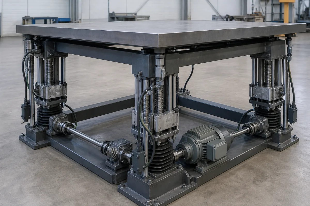
The illustrated table is lifted by a screw jack under each corner, the screws protected by bellows. One motor in the middle drives connecting shafts to bevel gearboxes that turn the drive through 90° into each jack. There is no controller keeping the corners level; the shafts do it, because as long as they turn, every jack is forced through the same stroke. ZIMM's engineering wiki describes how such a system is built, and Kelston's knowledge base how its motor is sized.
Covers height adjustment of support tables and platforms by mechanically synchronised screw jacks: system layout with a central motor, bevel gearboxes, connecting shafts, couplings and pedestal bearings, design principles, input speed and torque per jack, and system motor power. Choosing trapezoidal or ball screws, self-locking, brakes and duty cycle for a single lifting screw are on Screw-Driven Lifting Mechanism (1009); bevel gear geometry on Bevel Gears (4568); linear guidance on Linear Motion System (772). Office-chair height mechanisms share the name but are outside this page.
CNFX editorial research · Sources checked October 13, 2026 · 3 sources
One motor, T bevel gearboxes and connecting shafts: how four corners stay in step
ZIMM describes mechanical synchronisation as rigidly coupling every screw jack to a single central motor, so that all gearboxes move in exact synchronism while the shafts turn, without electronics.
ZIMM's bevel gearbox article gives the arrangement in words: one motor drives a central connecting shaft, T-shaped bevel gearboxes sit along it, and each deflects through 90° to drive the worm input shaft of a screw jack. Four jacks in an H configuration move as one unit, which is the layout in the illustration.
ZIMM notes that some of its bevel gearboxes can be turned through 180° to change the direction of rotation, which matters when a jack on the far side of a gearbox has to run the same way as its partner (editorial reading).
Component
Role (ZIMM)
Central drive motor
Provides the total power and drives all jacks together
Screw jacks
Number set by the load support points; trapezoidal or ball screws and different versions can be combined
Bevel gearboxes
Turn the horizontal connecting shafts through 90° onto the jacks' vertical input shafts and carry high torque compactly; ratios from 1:1 to 3:1
Connecting shafts
Carry torque from motor to gearboxes and between jacks; sized on the torque transmitted and the critical speed
Couplings
Join shaft ends and gearbox inputs, take up minor misalignment, damp shocks, can act as safety or disconnect elements
Pedestal bearings
Support long connecting shafts against deflection and vibration at higher speeds
Component series names are ZIMM's; the functions are the same in other makers' systems.
02
Design rules: drive from the middle, keep the load path short, align everything
ZIMM sets out three principles for a durable synchronised system.
In the illustrated table the motor sits between two jacks on one long side, close to the central position ZIMM recommends; the cross shafts then carry the drive to the far corners (editorial reading of the picture).
Since ZIMM attributes added backlash to every extra gearbox, shaft or bearing, the fewest-components rule also limits how far one corner can lag another (editorial reading).
Principle
Why (ZIMM)
Symmetrical load distribution
Place the motor so torques and loads on the connecting elements are as even as possible; a central input in the middle of a long shaft line is better than feeding from one end
Minimum number of components
Every extra gearbox, shaft or bearing adds small efficiency losses and backlash; direct, short load paths raise efficiency, stiffness and service life
Precise alignment
Jacks, bevel gearboxes, shafts and pedestal bearings at exactly the same height and in line; small misalignments stress the system, put radial forces on shafts and bearings and wear it out early
Mounting heights and alignment tolerances come from the system maker's installation instructions.
03
Sizing the motor: travel rate, torque per jack, and power for n jacks
Kelston's knowledge base sets out the calculation its system builder runs, and states that the formulae are not unique to that builder.
A worked example with assumed values, not catalogue data: a jack rated 20 N·m input torque at 50 kN nominal carrying 30 kN needs 20 × 30 ÷ 50 = 12 N·m; at 1,500 rpm that is 12 × 1,500 ÷ 9,550 = 1.88 kW per jack, and 7.5 kW for four before dividing by the system efficiency (Editorial calculation). With a 20:1 worm and a 6 mm pitch screw the travel rate is 0.3 mm/rev, so 300 mm/min of lift needs 1,000 rpm at the input (Editorial calculation).
ZIMM sizes connecting shafts on transmitted torque and critical speed; a shaft section near the motor carries the torque of every jack beyond it, one near a far corner only that jack's (editorial reading).
Quantity
Kelston formula
Worm input speed S_in (rpm)
Linear travel speed S_t (mm/min) ÷ travel rate S_r (mm/rev)
Travel rate
Set by worm wheel teeth over worm starts and the screw pitch; e.g. 40 teeth and 2 starts give a reduction of 20
Input torque T_in (N·m)
T_c × L_d ÷ L_n: torque at nominal capacity scaled by dynamic load over nominal capacity
Power per jack P_in (kW)
T_in × S_in ÷ 9550
System power P_s (kW)
P_in × number of jacks ÷ η, with η a system efficiency factor determined by measurement for the number of jacks
η has to come from the system maker; Kelston determines it by measurement.
04
What to give for a synchronised screw-jack lift
Paste it into your enquiry below or into an email to a maker, then replace every bracket.
Give the table or platform size and load, the load at each support point including off-centre loads, stroke, lifting speed, duty, positioning accuracy and whether the load must hold without power, and where the motor can sit. Ask for the jack size and screw type, bevel gearbox ratios and rotation directions, shaft sizes with critical speed and pedestal bearing spacing, coupling types, system efficiency and motor power, alignment tolerances, and limit switch or position feedback.
Explore company information and manufacturing capabilities, then discuss the scope of your project with a relevant supplier.
Share this page
Compiled and source-reviewed by the CNFX editorial team.
Each manufacturer above links to the page on that company's own website where the product is listed, with the date we checked it. How we source and review
· Page last updated 13 October 2026
Buyer questions
How do four screw jacks stay level without electronics?
ZIMM couples all jacks rigidly to one central motor through connecting shafts and bevel gearboxes, so while the shafts turn every jack moves in exact synchronism. [1]
Where should the motor go?
ZIMM recommends placing it so loads on the connecting elements are as even as possible, a central input in the middle of a long shaft line being better than feeding from one end. [1]
What does a bevel gearbox do in a jack system?
In ZIMM's description it deflects the drive from a connecting shaft through 90° into each jack's input shaft; ratios run from 1:1 to 3:1. [2]
How is the motor power for a group of jacks found?
Kelston multiplies the power for one jack, input torque × input speed ÷ 9,550, by the number of jacks and divides by a measured system efficiency factor. [3]
Sources and what still needs a direct check
Sources checked 2026-10-13. Two articles from a screw-jack maker's engineering wiki and a screw-jack maker's power calculation guide.