Editorial Technical Reference

Impeller/Piston Assembly

This page explains how Impeller/Piston Assembly is classified within Machinery and Equipment Manufacturing. Technical values and manufacturer relationships are research references; confirm the current specification and supplier evidence for each order.

Technical Definition & Core Assembly

A critical assembly combining impeller and piston functions for fluid pressurization in high-pressure pumps
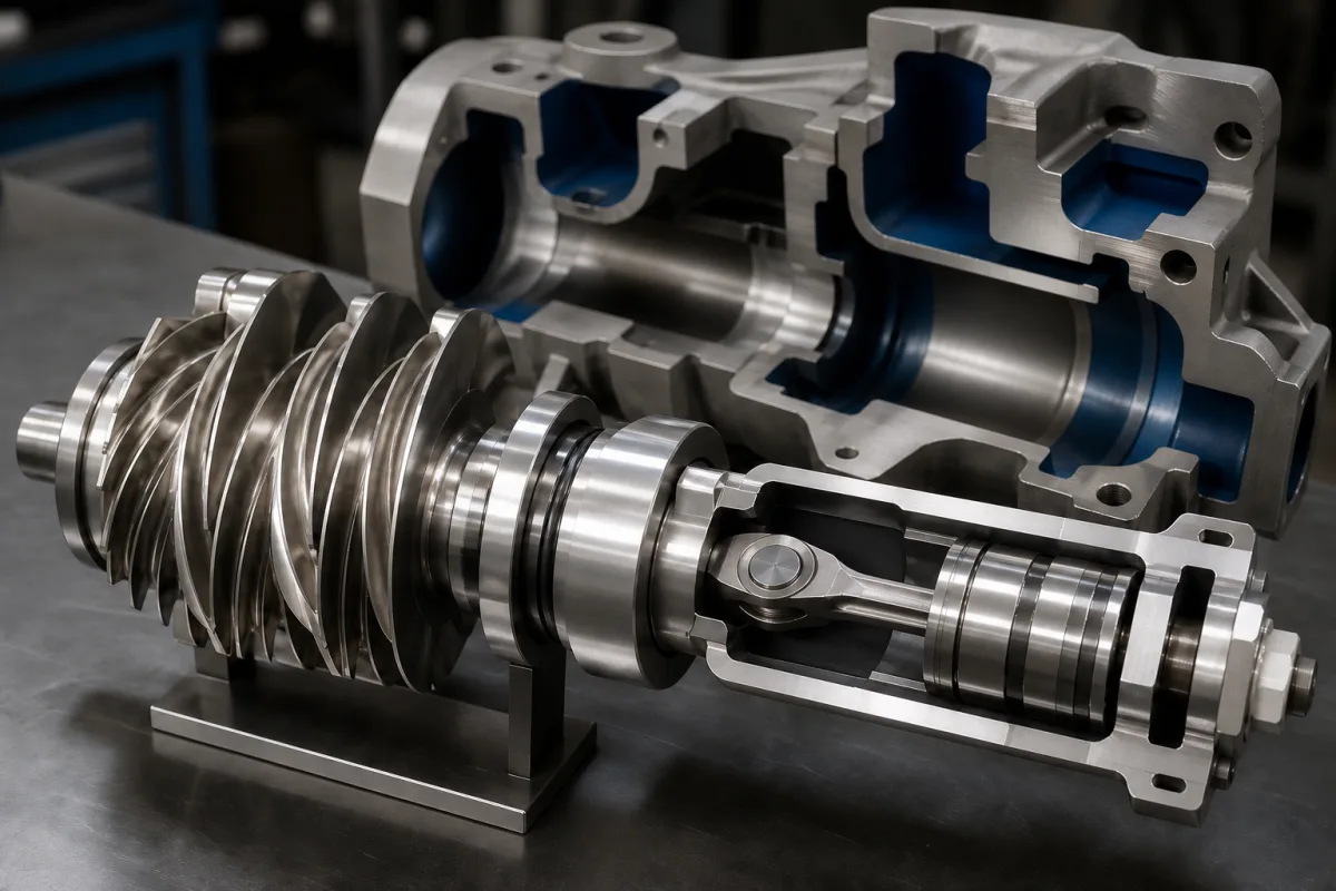
Representative product image. Confirm appearance and specifications with the manufacturer.

Product Specifications

Technical details and manufacturing context for Impeller/Piston Assembly

Definition
The Impeller/Piston Assembly is a key component within high-pressure pumps that integrates centrifugal impeller action with reciprocating piston motion to generate and maintain extreme fluid pressures. This assembly converts rotational energy into linear displacement while managing fluid flow dynamics, enabling the pump to achieve precise pressure control and consistent output across demanding industrial applications. The impeller section accelerates fluid radially outward using centrifugal force, while the piston section provides positive displacement through reciprocating motion. This combination allows for both high flow rates and precise pressure regulation, with the impeller handling initial fluid acceleration and the piston ensuring consistent volumetric displacement under varying pressure conditions. The assembly is typically manufactured from stainless steel, high-strength alloys, or ceramic coatings, depending on the application requirements. Key parameters include operating pressure (1.0–1.6 MPa), flow rate (10–50 L/min), impeller diameter (80–200 mm), piston stroke (20–60 mm), piston diameter (30–80 mm), rotational speed (1450–2900 rpm), temperature range (-20 to 80 °C), material grade (304–316 SS per ASTM A276), surface roughness (Ra 0.4–0.8 µm), balancing grade (G2.5–G6.3 per ISO 1940-1), weight (5–15 kg), and leakage rate (≤0.01 mL/min). These values are reference ranges and must be confirmed for the specific model and application. The assembly is designed for high-pressure pump systems where both high flow and precise pressure control are required. Selection inputs include the desired pressure and flow, fluid properties, and operating environment. Interfaces include the pump housing, drive shaft, and sealing systems. Verification questions should address material compatibility, dimensional tolerances, and performance testing. Maintenance signals include increased leakage, vibration, or noise, which may indicate seal wear or imbalance. Failure boundaries include exceeding the temperature or pressure limits, which can cause seal failure or structural damage. Always verify model-specific values and standards with the legal manufacturer or supplier.
Working Principle
The assembly operates through a dual-action mechanism: the impeller section accelerates fluid radially outward using centrifugal force, while the piston section provides positive displacement through reciprocating motion. This combination allows for both high flow rates and precise pressure regulation, with the impeller handling initial fluid acceleration and the piston ensuring consistent volumetric displacement under varying pressure conditions. The rotational energy from the drive shaft is transferred to the impeller, which imparts kinetic energy to the fluid. The piston, driven by a cam or crank mechanism, then displaces the fluid in a controlled manner, building pressure. The integration of these two actions enables the pump to handle a wide range of operating conditions, from low-pressure high-flow to high-pressure low-flow scenarios.
Common Materials
Stainless Steel, High-Strength Alloys, Ceramic Coatings
Technical Parameters
ParameterTypical rangeNotes & selection driver
Flow Rate10–50 L/minDepends on pump speed and impeller diameter
Impeller Diameter80–200 mmAffects head and flow characteristics
Piston Stroke20–60 mmDetermines displacement per revolution
Piston Diameter30–80 mmAffects force and sealing requirements
Rotational Speed1450–2900 rpmHigher speeds increase flow but reduce life
Temperature Range-20–80 °CExceeding limits may cause seal failure
Material Grade304–316 SS316 for corrosive mediaASTM A276
Surface RoughnessRa 0.4–0.8 µmCritical for sealing surfaces
Balancing GradeG2.5–G6.3Higher grade reduces vibrationISO 1940-1
Weight5–15 kgAffects handling and installation
Leakage Rate≤0.01 mL/minExceeding indicates seal wear

Ranges are indicative industry figures for RFQ preparation, not a supplier commitment. Confirm every value and standard with the legal manufacturer before ordering.

Components / BOM
  • Impeller Blade Part
    Accelerates fluid radially outward using centrifugal force
    Material: Stainless Steel
  • Piston Head Part
    Provides positive displacement through reciprocating motion
    Material: Hardened Alloy Steel
  • Drive Shaft Part
    Transfers rotational energy from motor to assembly
    Material: High-Strength Steel
  • Sealing Rings Part
    Prevents fluid leakage between moving components
    Material: PTFE or Ceramic
  • Cam or Crank Mechanism
    Turns the drive shaft's rotation into the piston's reciprocating stroke.

Applied To / Applications

This component is essential for the following industrial systems and equipment:

Industrial Ecosystem & Supply Chain Structure

Complementary Systems
Downstream Applications
Specialized Tooling

Application Fit & Sizing Matrix

Operational Limits
pressure: Up to 500 bar (7250 psi)
flow rate: 10-500 L/min
temperature: -40°C to 150°C
slurry concentration: Up to 30% solids by weight
Media Compatibility
✓ Hydraulic oils ✓ Water-based fluids ✓ Non-abrasive chemical solutions
Unsuitable: Highly abrasive slurries with >30% solids or corrosive acids
Sizing Data Required
  • Required flow rate (L/min)
  • Operating pressure (bar)
  • Fluid viscosity (cSt)

Reliability & Engineering Risk Analysis

Failure Mode & Root Cause
Fatigue cracking
Cause: Cyclic stress from pressure fluctuations and mechanical loading, often exacerbated by material imperfections or improper heat treatment.
Wear and clearance degradation
Cause: Abrasive particles in fluid media, inadequate lubrication, or misalignment leading to increased friction and loss of sealing efficiency.
Maintenance Indicators
  • Unusual vibration or knocking sounds during operation indicating imbalance or piston slap
  • Visible fluid leakage around seals or joints, or abnormal pressure/flow rate deviations
Engineering Tips
  • Implement predictive maintenance with vibration analysis and thermography to detect early-stage imbalances or wear
  • Ensure proper filtration of working fluids and maintain strict alignment tolerances during installation/repair

Indicative industry ranges for design and RFQ preparation. Confirm the exact figures and applicable standard with the manufacturer before specifying.

Compliance & Manufacturing Standards

Applicable Standards
ISO 1940-1:2003 (Balance quality requirements for rotors) ANSI/ASME B46.1-2019 (Surface Texture) DIN 1940-1 (Balancing of rotating rigid bodies)

Quoted from the published standard.

Manufacturing Precision
  • Bore diameter: +/-0.025mm
  • Surface roughness: Ra 0.8 μm
Quality Inspection
  • Dimensional verification via CMM (Coordinate Measuring Machine)
  • Hardness testing (Rockwell C scale)

Manufacturers of Impeller/Piston Assembly

Manufacturer profiles associated with Impeller/Piston Assembly.

Sourcing Impeller/Piston Assembly from China?
Tell us your specification and target quantity — we will match it against manufacturer records and come back with the factories that fit.
Request manufacturers We manufacture this

Manufacturer listings support early research and capability understanding. They are not certification, ranking, or transaction guarantees.

Technical documentation
Request current drawings, revision history, and a signed specification sheet.
Manufacturing capability
Verify equipment lists, process limits, capacity, and representative production evidence.
Inspection readiness
Confirm test methods, calibrated equipment, sampling plans, and traceable reports.
Supplier transparency
Check the legal entity, factory address, ownership, certifications, and direct contacts.

CNFX does not score or rank suppliers. Buyers must verify all claims and documents with the legal manufacturer before ordering.

Supply Chain Compatible Machinery & Devices

Hydraulic Press

Industrial machine using hydraulic pressure to compress, form, or assemble materials

Explore Specs →
Heavy-Duty CNC Plasma Cutting Machine

The Heavy-Duty CNC Plasma Cutting Machine is a standalone industrial device designed for cutting conductive metals such as steel, stainless steel, aluminum, and copper alloys.

Explore Specs →
Automated Powder Coating System

Integrated industrial system for applying dry powder coatings to metal substrates.

Explore Specs →
Centrifugal Pump Impeller

The centrifugal pump impeller is a critical rotating component that converts mechanical energy from the motor into kinetic energy in fluid systems.

Explore Specs →

Frequently Asked Questions

What is the primary function of the Impeller/Piston Assembly?

The assembly combines centrifugal impeller action with reciprocating piston motion to generate and maintain high fluid pressures in pumps. It converts rotational energy into linear displacement, enabling precise pressure control and consistent output.

What materials are commonly used for this assembly?

According to the directory, materials on file include stainless steel, high-strength alloys, and ceramic coatings. The specific material grade (e.g., 304–316 SS) should be confirmed based on the application and fluid compatibility.

What are the key parameters to consider when selecting this assembly?

Key parameters include operating pressure (1.0–1.6 MPa), flow rate (10–50 L/min), impeller diameter (80–200 mm), piston stroke (20–60 mm), piston diameter (30–80 mm), rotational speed (1450–2900 rpm), temperature range (-20 to 80 °C), material grade, surface roughness, balancing grade, weight, and leakage rate. These are reference ranges and must be verified for the specific model.

How can I verify the performance and compliance of this assembly?

You should consult the legal manufacturer or supplier to confirm model-specific values and standards. The directory lists standards such as ASTM A276 for material grade, and ISO 1940-1 for balancing grade, but these are references for procurement and verification, not proof of certification.

Data Basis

Editorial classification, named public sources where available, and source-reviewed manufacturer records.

Preliminary Technical Classification
This page supports structured research, RFQ preparation, and supplier evaluation. It does not replace buyer-led supplier qualification, standards review, or technical approval.
Buyer enquiry

Request manufacturing insight for Impeller/Piston Assembly

Ask for use case, specification boundaries, supplier type, and RFQ preparation information for this product.

Where it goes
Straight to the CNFX editorial desk, and to the manufacturer if this product is linked to a claimed profile. Nothing is broadcast to a supplier list.
Your details stay here
We do not sell or rent enquiry data, and we do not add you to a mailing list. Used only to answer this request.
No commission, no middleman
CNFX is a directory. We take no cut of any order and never negotiate on a supplier's behalf.
What we don't claim
A listing is not an endorsement. Qualify every supplier and verify every figure yourself before ordering.

Your business information is used only to process this request.

Thank you! Your message has been sent. We'll respond within 1–3 business days.
Sorry, we couldn't send your message. Please try again, or email us at contact@cnfx.com.

Need to Manufacture Impeller/Piston Assembly?

Compare manufacturer profiles with relevant product and process capability.

Previous Product
Z-axis Ram/Spindle
Last Product
Get QuotesChat