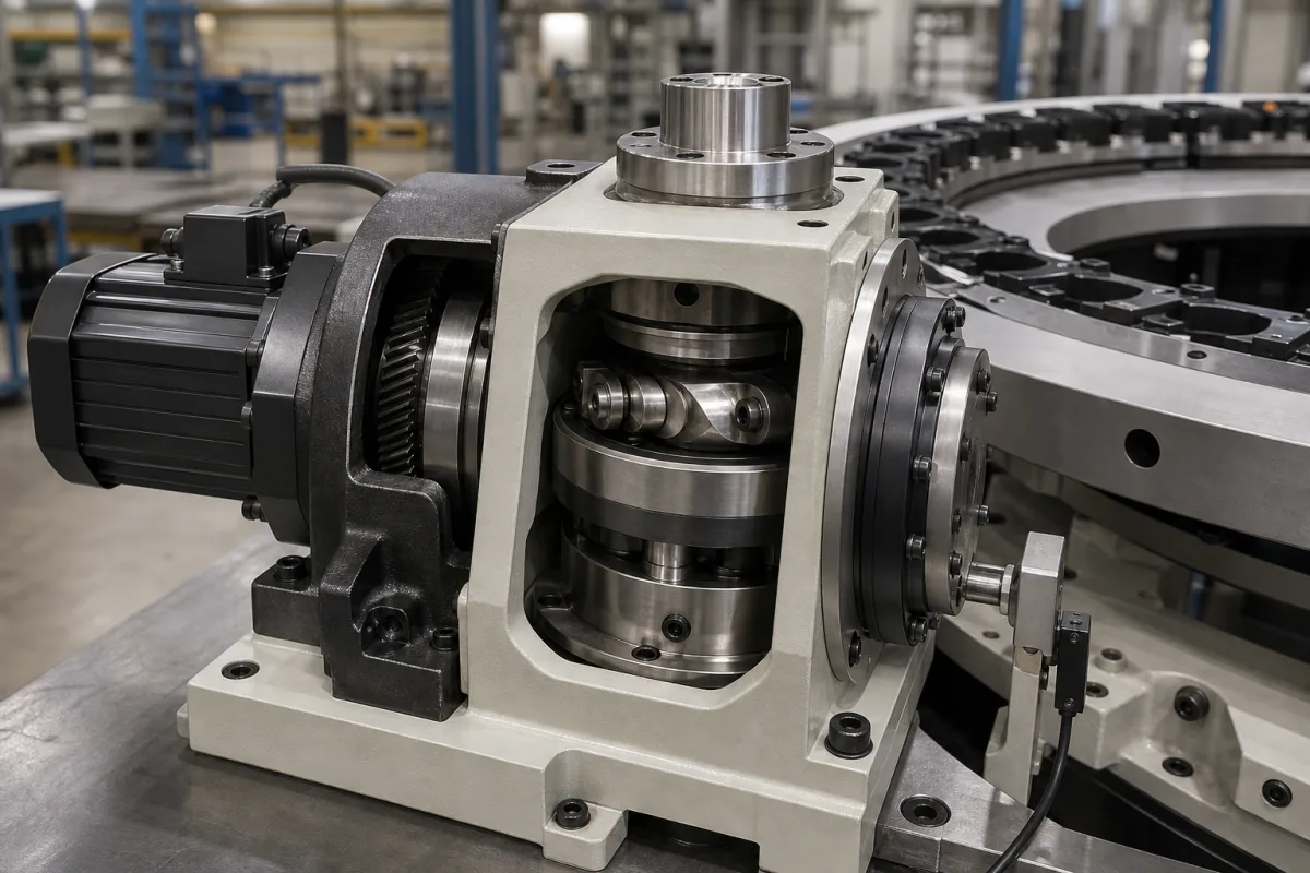
Indexing mechanism (mechanical cam indexer that steps a tool magazine or dial from station to station)
Mechanical cam indexers that step tool magazines, dials and carousels · stops, index period and dwell, modified sine and other motion laws, single- and multi-cycle cams, continuous or cycle-on-demand running, and overlapping motion to cut inertia torque
A cam indexer turns a motor's constant rotation into stop-and-go motion: the output moves one station, rests, moves again. On a tool magazine, dial table or carousel it decides how many positions there are, how long each move takes, how hard the load is accelerated, and how precisely each station is held. Specify the number of stops, the index period and dwell, the motion law, the cam type, and whether it runs continuously or stops between cycles.
Mechanical cam indexers (paradromic, barrel and globoidal / roller-gear cams) that index tool magazines, dial tables and carousels: stops, index period and dwell, motion laws, single- and multi-cycle cams and operating modes. Tool magazines as a whole are covered on the CNC tool magazine page; CNC rotary tables on the Rotary table page; servo ring-gear carousel positioning on the Station positioning system for indexing carousels page; slewing-ring bases on the Rotating platform for carousels page.
CNFX editorial research · Sources checked October 12, 2026 · 3 sources
Nolte's glossary of indexing mechanisms defines the terms an indexer is ordered by: the number of stops sets after how many steps the output completes one revolution, and "Step angle = 360 degrees / stop number"; the indexing angle and the dwell angle are rotations of the input shaft during the move and during standstill, and they add up to the period angle. [3] CDS codes an indexer as series, size, number of stops and index period, for example "IT - 200 - 4 - 270", where 4 is the number of stops and 270 the index period angle. [2]
Editorial calculation with that example and a continuously running single-cycle cam at 60 rpm (one second per revolution): a 270° index period gives 0.75 s of movement and 0.25 s of dwell per station, and four stops give a 90° step at the output. [2][3]
State the number of stations, the time available per cycle, the dwell needed at each station (for tool change, pick or process), and the inertia and friction of the load.
02
Motion law, cam type and the torque saved by overlap
Robert Zaruba and Stephen Gough of CDS, writing in Machine Design, call modified sine motion "the industry standard", combining a low acceleration factor with a gradual change from acceleration to deceleration; modified sine with constant velocity lowers the velocity factor, modified trapezoid lowers the acceleration factor further, and asymmetric modified sine uses longer deceleration. Paradromic, barrel and globoidal cams dominate; paradromic output runs on the input axis, barrel and globoidal at right angles, and globoidal cams can also oscillate. [1]
In a single-cycle cam one camshaft revolution gives one index; in a multi-cycle cam it gives two or more, and "multi-cycle cam indexers exhibit an inherent margin of error that must be factored into overall machine design". [1]
On timing, they note that with modified sine "the first 15% of the index period produces only about 2% of output displacement", so selecting a 120° index period where 90° is needed gives 15° of overlap at each end and "substantially reduces torque requirements, caused by the inertia load, by more than 50%". Running continuously fixes the index-dwell relationship and can be tied to the machine line shaft; stopping the camshaft in dwell (cycle on demand) lets dwell time vary. [1][2]
Ask for the displacement chart of the chosen motion law and index period so overlapping machine motions can be timed against it.
03
Cam indexer details
Paste it into your enquiry below or into an email to a maker, then replace every bracket.
Application: [tool magazine; dial; carousel]
Stops: [number]
Cycle: [index period; dwell; cycles per minute]
Motion law: [modified sine; MS with constant velocity; modified trapezoid]
Cam: [paradromic; barrel; globoidal; single or multi-cycle]
Mode: [continuous; cycle on demand]
Load: [inertia; friction; external torque]
Output: [shaft; flange; dial]
Explore company information and manufacturing capabilities, then discuss the scope of your project with a relevant supplier.
Share this page
Compiled and source-reviewed by the CNFX editorial team.
Each manufacturer above links to the page on that company's own website where the product is listed, with the date we checked it. How we source and review
· Page last updated 13 October 2026
Buyer questions
Which motion law is standard for indexers?
CDS engineers describe modified sine as the industry standard because of its low acceleration factor and smooth transition. [1]
Why choose a longer index period than needed?
Overlapping, for example 120° where 90° is needed, cuts inertia torque by more than 50%, according to CDS. [1][2]
CDS notes multi-cycle indexers have an inherent margin of error to factor into the machine design. [1]
Sources and what still needs a direct check
Sources checked 2026-10-12. Machine Design published CDS engineers' article on indexing cams; the CDS technical guide is read from a ManualsLib copy; Nolte NC-Kurventechnik publishes a glossary of indexing mechanisms.