Electric linear actuators for automation, labelling, pick-and-place and pressing · rod-style vs rodless slide, ball screw vs roller screw vs belt drive, force, speed and stroke, duty cycle, side loads, environment, integrated controllers
An electric linear actuator moves a load in a straight line using a motor driving a screw or belt — for example to lower a labelling head, push parts, or move a tool across a conveyor in an automated cell. Ask three things first: the force, speed, stroke and duty cycle of the move; whether the actuator must guide and carry the load (rodless slide) or only push it (rod style); and the accuracy, environment and controls the application needs.
Electric linear actuators for industrial automation — rod-style and guide-rod actuators, rodless slides and slide tables, screw- and belt-driven — with motors, controllers and encoders. Pneumatic cylinders and actuators (see pneumatic actuator), hydraulic cylinders, voice coil actuators (see voice coil motor) and furniture or automotive DC actuators are outside this page except where compared.
CNFX editorial research · Sources checked October 12, 2026 · 4 sources
Tolomatic, an actuator maker, explains that the first choice is between a rod-style actuator, whose rod extends and retracts like a hydraulic cylinder, and a rodless actuator, whose slide moves along an extrusion. Rod-style actuators are screw-driven with the thrust rod in line with the screw and nut, provide higher forces for pushing, pulling and pressing, and offer ingress protection without a shield; they suit replacing hydraulics in motion simulators, bearing presses, mould ejectors and extruders, and pneumatics in pivoting and gate positioning. Rodless actuators guide and support the load without external guides, are more compact, and can be screw- or belt-driven; belt drive allows 100–200 in/s against 20–40 in/s for rod styles and longer lengths, while screw-driven rodless units give more force but are limited in stroke and speed. Rodless types suit gantries, long moves, cutting and tight spaces. [1] SMC's electric actuator line, for example, includes rod and guide-rod types, ball-screw slider types, high-rigidity and low-profile sliders, compact slide tables, miniature rod and slide types, rotary tables and grippers, with battery-less absolute encoders and integrated controllers. [2]
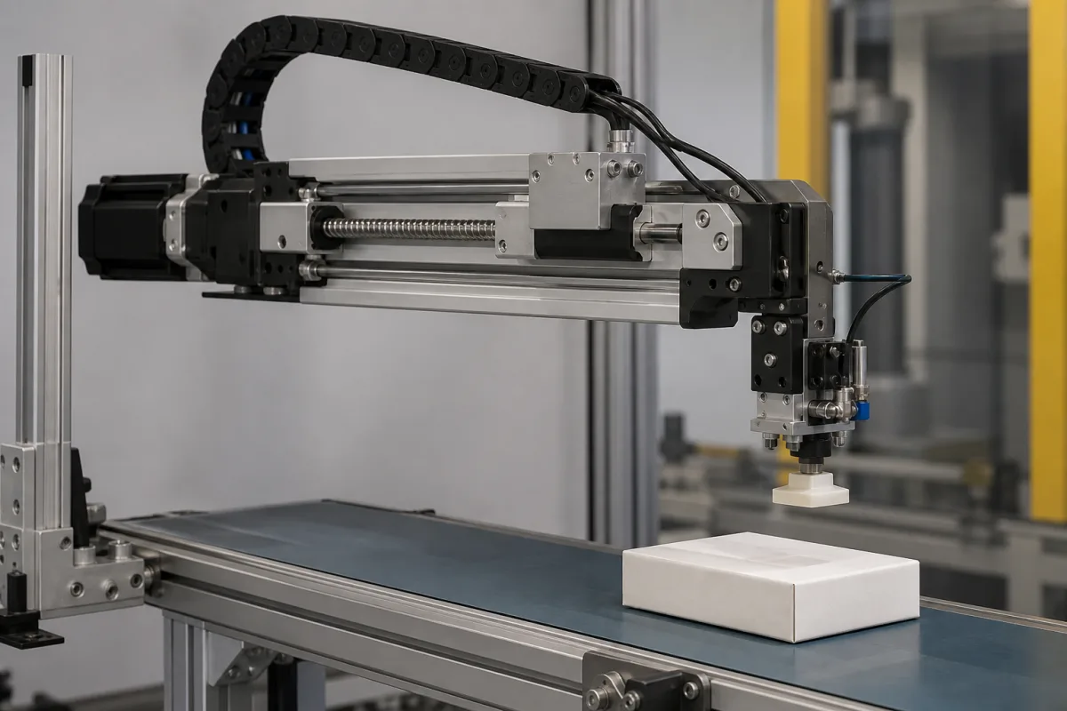
Editorial note: a labelling or pick-and-place head moved across a conveyor, as in a gantry, matches Tolomatic's description of rodless use; a pressing stroke matches rod style. Ask suppliers to confirm the choice against your load and moment calculations. [1]
Give the supplier the load mass and orientation, force (continuous and peak), stroke, speed and acceleration, cycle time and duty cycle, positioning accuracy and repeatability, side and moment loads, rod or rodless and screw or belt preference, motor and controller (integrated, fieldbus, I/O), encoder type, environment (dust, washdown, temperature, IP), mounting, cable length, and quantity.
02
Size force, speed, duty and screw type
Tolomatic advises sizing an electric actuator as precisely as possible, because oversizing costs rise quickly, unlike hydraulic or pneumatic systems that are easier to oversize; to know velocity, critical speeds and required accuracy; to match the actuator to the duty cycle — continuous duty differs from occasional moves; to avoid side loading by adding guides and compliance for self-alignment; to match peak forces; and to check operating conditions such as dust, paint or water spray. Ball screws have less contact area but low friction and little heat, suiting high speed and positioning at lower cost; roller screws have more contact area for larger loads and pressing, with more heat and a longer working life. Sizing charts specify screw type (ball or solid nut), lead (screw turns per inch of travel) and lead accuracy, which matters for repeated pressing. [1]
Editorial note: give the supplier the full motion profile — not only maximum force — so it can check screw life, critical speed and motor sizing together. [1]
For the screw itself, THK's ball screw selection guide calculates the nominal life L10 from the basic dynamic load rating Ca and the axial load Fa, where Ca is the constant axial load at which identical screws reach a rated life of 10⁶ revolutions. To cover vibration, shock and load swings it applies a load factor fW of 1–1.2 for faint vibration at up to 0.25 m/s, 1.2–1.5 for weak vibration at 0.25–1 m/s, 1.5–2 for medium vibration at 1–2 m/s and 2–3.5 for strong vibration above 2 m/s. It notes that the estimate assumes ideal mounting and good lubrication, that a preloaded nut must count the preload, and that stepped loads are reduced to an equivalent average axial load. [3]
Editorial calculation: on a 10 mm-lead screw, the 10⁶ revolutions behind the Ca rating equal 10 km of nut travel (10⁶ × 10 mm); a 20 mm lead doubles the travel for the same revolutions but halves the thrust available from the same motor torque. [3]
03
Compare what suppliers offer
The manufacturer card below states what the reviewed source shows.
When requesting quotations, ask each supplier for force-speed curves, rated life at your duty, repeatability, allowable moments for rodless slides, IP rating and controller options.
04
Check the screw's allowable axial load and rotational speed
MISUMI's ball screw selection guide keeps the axial load on the screw at or below an allowable axial load derived from the buckling load. The rotational speed, set by feed rate and lead, must stay at or below an allowable speed set by the shaft's critical speed and by the DmN limit for the balls in the nut; the allowable speed is 80% of the critical speed, where rotation resonates with the shaft's natural frequency. [4]
In its worked examples, a φ15 mm screw with a 5 mm lead, mounted fixed–fixed (coefficient m = 19.9) with an 820 mm point-of-load distance and a 12.5 mm root diameter, has a maximum axial load of 7,225 N. Mounted fixed–supported (coefficient g = 15.1) over 790 mm, the same screw is limited to 3,024 min⁻¹, and a φ20 mm shaft with 1,500 mm between fixed–supported supports reads 1,076 min⁻¹ from its chart. [4]
Editorial calculation: 3,024 min⁻¹ × 5 mm lead = 15,120 mm/min, about 252 mm/s (≈ 9.9 in/s), below the 20–40 in/s Tolomatic gives for rod-style actuators [1]. Ask the supplier for the mounting configuration, support distance, and resulting allowable load and speed at your stroke. [4]
05
Trace the actuator
This is a functional reference built from the sources cited; it is not one maker's design.
Element
Role
Fix in the order
Drive
Ball screw, roller screw or belt; screw life from Ca. [1][3]
Fill the specification fields with values for your project
A linear actuator quotation needs values for your project. The table explains each field, gives published values where a reviewed source states them, and says what to obtain from the supplier.
The manufacturer below lists electric linear actuators on its own website; each card links to the page reviewed. Confirm ratings, materials and approvals for your order.
Diyue Precision Technology (Suzhou) Co., Ltd.
Manufacturing site to be confirmed for the order
Lists servo electric cylinders alongside precision planetary reducers and linear modules.
Explore company information and manufacturing capabilities, then discuss the scope of your project with a relevant supplier.
Share this page
Compiled and source-reviewed by the CNFX editorial team.
Published product pages show what a company offers, not tested performance. Confirm the legal seller, factory and scope for your order. How we source and review
· Page last updated 13 October 2026
Buyer questions
Rod-style or rodless actuator?
Tolomatic says rod styles give higher force for pushing and pressing; rodless units guide the load, are compact and, belt-driven, run faster and longer. [1]
How fast are electric linear actuators?
Tolomatic gives 20–40 in/s for rod styles and 100–200 in/s for belt-driven rodless actuators. [1]
Ball screw or roller screw?
Ball screws suit speed and positioning at lower cost; roller screws take larger loads and last longer under pressing. [1]
How does vibration affect actuator screw life?
THK applies a load factor fW from 1–1.2 for faint vibration at low speed up to 2–3.5 for strong vibration above 2 m/s when calculating ball screw life. [3]
What limits the speed of a ball-screw actuator?
MISUMI's ball screw guide sets the allowable rotational speed at 80% of the shaft's critical speed and also checks the DmN value of the balls in the nut; its φ15 mm, 5 mm-lead example on a 790 mm fixed–supported span is limited to 3,024 min⁻¹. [4]
Sources and what still needs a direct check
Sources checked 2026-10-12. Tolomatic and SMC are actuator makers describing selection and their own ranges.