Editorial Technical Reference

Machine Vision Camera Array

This page explains how Machine Vision Camera Array is classified within Machinery and Equipment Manufacturing. Technical values and manufacturer relationships are research references; confirm the current specification and supplier evidence for each order.

Technical Definition & Core Assembly

A multi-camera system integrated within a Quality Inspection Module for comprehensive visual inspection of manufactured products.
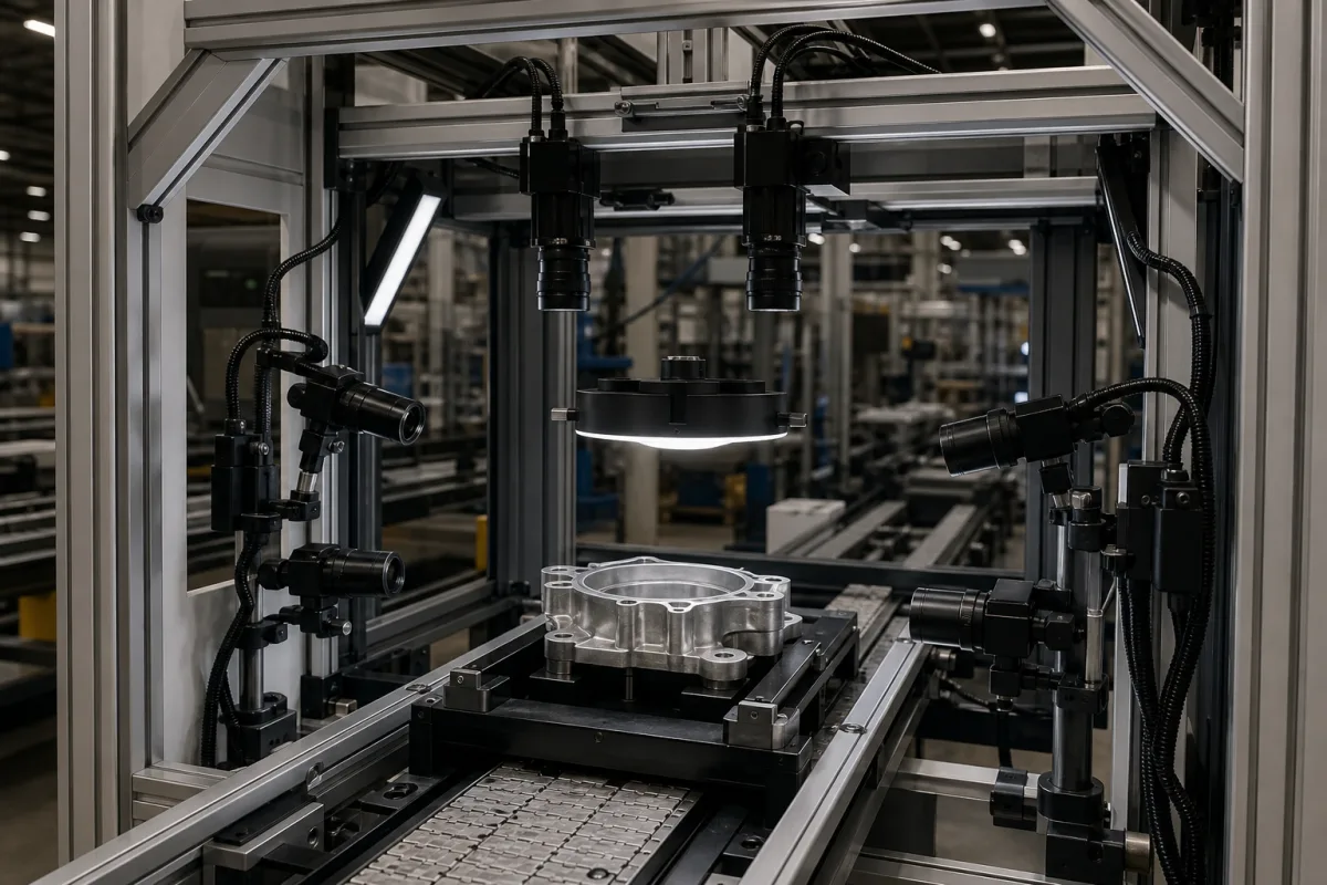
Representative product image. Confirm appearance and specifications with the manufacturer.

Product Specifications

Technical details and manufacturing context for Machine Vision Camera Array

Definition
The Machine Vision Camera Array is a critical component of the Quality Inspection Module, consisting of multiple synchronized industrial cameras strategically positioned to capture high-resolution images from various angles. It enables automated detection of defects, dimensional verification, surface inspection, and quality assessment across production lines, ensuring products meet specified standards before proceeding to subsequent manufacturing stages. The array is designed for integration into automated inspection systems, providing real-time image acquisition and processing capabilities. It is typically used in manufacturing environments where consistent, high-speed quality control is required. The system's configuration can be adapted to different inspection tasks, with the number of cameras ranging from 4 to 16, depending on the coverage needed. Each camera offers a resolution between 5 and 20 megapixels, allowing for fine defect detection. Frame rates vary from 30 to 120 frames per second, suitable for high-speed production lines. The field of view can be adjusted between 60 and 120 degrees to accommodate larger parts. Inspection accuracy is specified at ±0.05 mm at the working distance, which can be set from 200 to 1000 mm. The operating temperature range is 0 to 50 °C, non-condensing. The housing is rated IP54 to IP65 for dust and water resistance, according to IEC 60529. The system requires a stabilized 24 V DC supply (±10%) and consumes between 50 and 150 W, depending on camera count and lighting. Data transfer is via GigE or USB3.0 interfaces. The weight, without mounting bracket, ranges from 5 to 20 kg. Materials used include aluminum alloy housing, optical glass lenses, CMOS/CCD sensors, and copper wiring. For specific applications, verify model-specific values and standards with the legal manufacturer or supplier.
Working Principle
The array operates by synchronizing multiple industrial cameras to simultaneously capture images of products as they pass through the inspection area. These images are processed in real-time by vision software algorithms that analyze features such as dimensions, color, texture, and presence of defects. The system compares captured data against predefined quality parameters to identify non-conforming items. The synchronization ensures consistent lighting and timing, enabling accurate measurements. The working principle relies on the precise positioning of cameras and the calibration of their fields of view to cover the required inspection area. The system can be configured to trigger image capture based on product presence, using sensors or encoders. The captured images are then transmitted to a processing unit via the interface, where algorithms perform the analysis. The results are used to reject defective products or to provide feedback for process control. The system's accuracy depends on factors such as camera resolution, lens quality, lighting conditions, and the stability of the mounting structure. Regular calibration and maintenance are necessary to maintain performance.
Common Materials
Aluminum alloy housing, Optical glass lenses, CMOS/CCD sensors, Copper wiring
Technical Parameters
ParameterTypical rangeNotes & selection driver
Number of Cameras4–16 pcsConfigurable based on inspection coverage
Resolution per Camera5–20 MPHigher resolution for fine defect detection
Frame Rate30–120 fpsHigher for high-speed production lines
Field of View60–120 °Wider for larger parts
Inspection Accuracy±0.05 mmAt working distance
Working Distance200–1000 mmAdjustable
Operating Temperature0–50 °CNon-condensing
Ingress ProtectionIP54–IP65Dust and water resistantIEC 60529
Supply Voltage24 ±10% V DCStabilized power required
Power Consumption50–150 WDepends on camera count and lighting
InterfaceGigE / USB3.0For data transfer
Weight5–20 kgWithout mounting bracket

Ranges are indicative industry figures for RFQ preparation, not a supplier commitment. Confirm every value and standard with the legal manufacturer before ordering.

Components / BOM
  • Industrial Camera Module
    Captures high-resolution digital images of products under inspection
    Material: Aluminum housing with optical glass
  • Mounting Bracket Part
    Secures cameras in precise positions within the array configuration
    Material: Stainless steel
  • Synchronization Controller
    Coordinates timing and triggering of all cameras in the array
    Material: PCB with electronic components
  • Lighting Module
    Provides consistent illumination for optimal image capture
    Material: LED arrays with diffusers

Applied To / Applications

This component is essential for the following industrial systems and equipment:

Industrial Ecosystem & Supply Chain Structure

Complementary Systems
Downstream Applications
Specialized Tooling

Application Fit & Sizing Matrix

Operational Limits
pressure: Atmospheric pressure only (non-pressurized environment)
other spec: Maximum vibration tolerance: 2G, IP65 ingress protection rating
temperature: 0°C to 50°C operating range
Media Compatibility
✓ Electronics assembly lines ✓ Pharmaceutical packaging inspection ✓ Automotive component manufacturing
Unsuitable: High-particulate foundry environments with airborne metal dust
Sizing Data Required
  • Product inspection area dimensions (mm)
  • Required inspection resolution (pixels/mm)
  • Production line speed (units/minute)

Reliability & Engineering Risk Analysis

Failure Mode & Root Cause
Lens Contamination
Cause: Accumulation of dust, oil mist, or particulates on optical surfaces, degrading image quality due to inadequate environmental sealing or improper maintenance intervals.
Sensor Degradation
Cause: Thermal stress from continuous operation or ambient temperature fluctuations leading to pixel defects, reduced sensitivity, or color calibration drift.
Maintenance Indicators
  • Persistent image artifacts (e.g., streaks, blurring, or discoloration) not resolved by cleaning.
  • Intermittent connectivity or frame drops in the video feed, indicating potential hardware or firmware instability.
Engineering Tips
  • Implement positive pressure purge systems with filtered air to maintain clean optical paths and control internal humidity.
  • Establish regular thermal monitoring and active cooling management to stabilize sensor operating temperatures within manufacturer specifications.

Indicative industry ranges for design and RFQ preparation. Confirm the exact figures and applicable standard with the manufacturer before specifying.

Compliance & Manufacturing Standards

Applicable Standards
ISO 12233:2017 (Photography - Electronic still-picture imaging - Resolution and spatial frequency responses) IEC 62471:2006 (Photobiological safety of lamps and lamp systems) CE marking for electromagnetic compatibility (EMC) and low voltage directives

Quoted from the published standard.

Manufacturing Precision
  • Lens focal length: +/-0.5%
  • Sensor alignment flatness: 0.05mm across array
Quality Inspection
  • MTF (Modulation Transfer Function) measurement for optical performance
  • Thermal cycling test for environmental durability

Manufacturers of Machine Vision Camera Array

Manufacturer profiles associated with Machine Vision Camera Array.

Sourcing Machine Vision Camera Array from China?
Tell us your specification and target quantity — we will match it against manufacturer records and come back with the factories that fit.
Request manufacturers We manufacture this

Manufacturer listings support early research and capability understanding. They are not certification, ranking, or transaction guarantees.

Technical documentation
Request current drawings, revision history, and a signed specification sheet.
Manufacturing capability
Verify equipment lists, process limits, capacity, and representative production evidence.
Inspection readiness
Confirm test methods, calibrated equipment, sampling plans, and traceable reports.
Supplier transparency
Check the legal entity, factory address, ownership, certifications, and direct contacts.

CNFX does not score or rank suppliers. Buyers must verify all claims and documents with the legal manufacturer before ordering.

Supply Chain Compatible Machinery & Devices

Automated Powder Coating System

Integrated industrial system for applying dry powder coatings to metal substrates.

Explore Specs →
Centrifugal Pump Impeller

The centrifugal pump impeller is a critical rotating component that converts mechanical energy from the motor into kinetic energy in fluid systems.

Explore Specs →
High-Precision CNC Laser Cutting Machine

Computer-controlled industrial machine using focused laser beams to cut sheet metal with micron-level accuracy.

Explore Specs →
Industrial-Grade Hydraulic Cylinder Piston Rod

This industrial-grade piston rod is a precision-ground cylindrical component designed for use in hydraulic cylinders.

Explore Specs →

Frequently Asked Questions

What is the typical number of cameras in the array?

The number of cameras is configurable based on inspection coverage, typically ranging from 4 to 16 units. The exact count depends on the size of the inspection area and the required level of detail.

What is the maximum frame rate for high-speed production lines?

The frame rate can be set between 30 and 120 frames per second. Higher frame rates are suitable for faster production lines, but the actual achievable rate may depend on the camera model and processing capabilities.

What is the inspection accuracy?

The inspection accuracy is specified as ±0.05 mm at the working distance. This value is a reference and should be verified for the specific configuration and application with the manufacturer.

What are the environmental and electrical requirements?

The system operates in temperatures from 0 to 50 °C (non-condensing) and has an ingress protection rating of IP54 to IP65. It requires a stabilized 24 V DC supply (±10%) and consumes between 50 and 150 W depending on configuration.

Data Basis

Editorial classification, named public sources where available, and source-reviewed manufacturer records.

Preliminary Technical Classification
This page supports structured research, RFQ preparation, and supplier evaluation. It does not replace buyer-led supplier qualification, standards review, or technical approval.
Buyer enquiry

Request manufacturing insight for Machine Vision Camera Array

Ask for use case, specification boundaries, supplier type, and RFQ preparation information for this product.

Where it goes
Straight to the CNFX editorial desk, and to the manufacturer if this product is linked to a claimed profile. Nothing is broadcast to a supplier list.
Your details stay here
We do not sell or rent enquiry data, and we do not add you to a mailing list. Used only to answer this request.
No commission, no middleman
CNFX is a directory. We take no cut of any order and never negotiate on a supplier's behalf.
What we don't claim
A listing is not an endorsement. Qualify every supplier and verify every figure yourself before ordering.

Your business information is used only to process this request.

Thank you! Your message has been sent. We'll respond within 1–3 business days.
Sorry, we couldn't send your message. Please try again, or email us at contact@cnfx.com.

Need to Manufacture Machine Vision Camera Array?

Compare manufacturer profiles with relevant product and process capability.

Previous Product
Z-axis Ram/Spindle
Last Product
Get QuotesChat