Machine vision inspection · Pixels per feature, exposure against conveyor speed, EMVA 1288 camera data
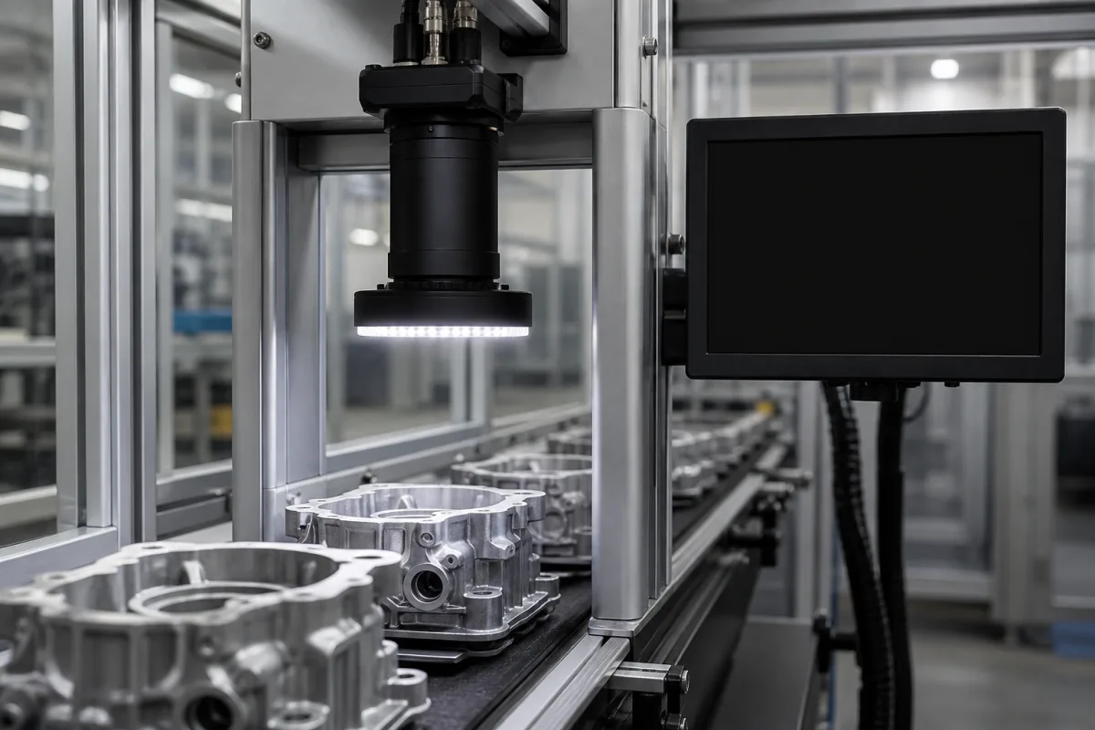
A machine vision system for inspection combines an industrial camera, lens, lighting and image-processing hardware and software to check parts automatically on a production line. Ask three things first: how many pixels the system puts across the smallest defect or feature it must find, how short the exposure or strobe is at your line speed, and which camera performance data, measured to EMVA 1288, backs the camera choice.
Camera-based inspection, measurement and guidance systems for production lines, and their cameras, lenses and lighting. Stand-alone vision measuring machines (VMMs), barcode scanners, consumer camera modules and security cameras are outside this page.
CNFX editorial research · Sources checked October 12, 2026 · 4 sources
Size the camera by pixels across the smallest feature
1stVision, a machine vision camera distributor, states that finding an edge needs at least 2 pixels given excellent contrast, and that a robust system ideally has 3–4 pixels across an edge or feature. Its method divides the smallest feature by the pixels wanted across it to get the spatial resolution, then divides the field of view by that to get the sensor pixels needed: a 0.25 mm pin hole on a 20 mm part, with a 40 mm × 30 mm field of view to allow for misplacement and 4 pixels across the hole, needs 0.25 / 4 = 0.0625 mm per pixel and 40 / 0.0625 = 640 pixels in X. [1]
1stVision notes that the method assumes optimum conditions and a lens that does not limit resolution, and that the pixels actually required depend on lighting, optics and the processing algorithms. [1]
Editorial calculation: for a casting inspected in a 200 mm × 150 mm field of view, finding a 0.5 mm defect with 4 pixels across it needs 0.5 / 4 = 0.125 mm per pixel, so 200 / 0.125 = 1,600 pixels in X and 150 / 0.125 = 1,200 pixels in Y — about a 1,600 × 1,200 (1.9 megapixel) sensor before any margin. The part, field and defect sizes are assumed examples; use your own. [1]
Give the supplier sample good and defective parts, the smallest defect or tolerance to detect, the field of view including part placement variation, line speed and parts per minute, part surface (machined, cast, reflective, dark), working distance and space for camera and lights, reject or PLC interface, and data and traceability requirements.
02
Freeze the motion with exposure or strobe
Texas Instruments' technical note on LED lighting for machine vision states that holding motion blur to one pixel or less is the best approach, by shortening exposure time through the camera shutter, the strobe duration or both: tE = FOV / (v × NP), with field of view and pixel count both taken in the direction of motion. Its example — 12.8 mm field of view, 1,280 pixels, conveyor at 3 m/s — gives 3.3 µs. [2]
TI's LED lighting control reference design described in the note drives a string of five high-power LEDs at 200 mA to 2.4 A, with up to 40 W pulse power, strobe durations as short as 200 ns and frame rates up to 10 kHz, from an 8–36 V input with a 15 W input power limit and an isolated trigger interface. [2]
Editorial calculation: for the casting example above at 0.125 mm per pixel on a conveyor moving at 0.5 m/s (500 mm/s), one pixel of blur is reached in 0.125 / 500 s = 250 µs, so exposure or strobe should be at or below 250 µs. The conveyor speed is an assumed example. [2][1]
03
Ask for EMVA 1288 camera data
EMVA 1288, the European Machine Vision Association's standard for characterising image sensors and cameras, took effect as Release 4.0 in June 2021, split into a Linear document for cameras with a linear response and a General document for wider classes of cameras. [4][3]
Release 4.0 Linear lists sensitivity, temporal noise and linearity; nonuniformity; defect pixel characterisation; and dark current as mandatory measurements, with temperature dependence of dark current and spectral quantum efficiency as optional. It defines the absolute sensitivity threshold as the mean number of photons giving a signal-to-noise ratio of 1 and the dynamic range as saturation exposure divided by that threshold, and notes that saturation capacity “is normally lower than the full-well capacity”. The Linear method cannot be used where preprocessing such as debayering, denoising or edge sharpening breaks its noise assumptions. [3]
Editorial note: comparing two cameras' EMVA 1288 datasheets is more meaningful than comparing pixel counts alone, because the same resolution can come with very different noise and dynamic range.
04
Compare what suppliers offer
Suppliers linked to this page list machine vision inspection machines or components for them; each card links to the page reviewed.
Listings include complete CCD inspection and sorting machines as well as SWIR cameras and machine vision lenses; ask a component supplier who integrates the lighting, software and reject handling.
05
Trace the system components
This is a functional reference built from the sources cited; it is not one maker's specification.
Fill the specification fields with values for your parts
A machine vision quotation needs values for your parts and line. The table explains each field, gives published values where a reviewed source states them, and says what to obtain from the supplier.
Field
What it means and published values
Ask the supplier for
Resolution (megapixels)
Set by field of view ÷ (feature ÷ pixels per feature). [1]
Sensor pixels in X and Y.
Frame rate (fps)
Images per second; the TI lighting design supports frame rates up to 10 kHz. [2]
Explore company information and manufacturing capabilities, then discuss the scope of your project with a relevant supplier.
Share this page
Compiled and source-reviewed by the CNFX editorial team.
Published product pages show what a company offers, not tested performance. Confirm the legal seller, factory and scope for your order. How we source and review
· Page last updated 13 October 2026
Buyer questions
How many pixels does a vision system need across a defect?
1stVision states at least 2 pixels to find an edge with excellent contrast, and ideally 3–4 for robustness. [1]
How do I calculate camera resolution for inspection?
Divide the smallest feature by the pixels wanted across it, then divide the field of view by that; 1stVision's example gives 640 pixels for a 40 mm field. [1]
How short must the exposure be on a moving line?
TI gives exposure = field of view / (speed × pixels) for one pixel of blur; its 3 m/s example needs 3.3 µs. [2]
What is EMVA 1288?
The EMVA standard for measuring and presenting camera and sensor performance; Release 4.0 took effect in June 2021. [4][3]
Sources and what still needs a direct check
Sources checked 2026-10-12. 1stVision is a camera distributor and Texas Instruments a component maker, each explaining a design method; EMVA 1288 is the industry standard for camera characterisation, published by the European Machine Vision Association.