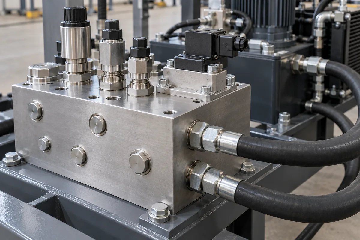
Hydraulic manifold blocks · Material against operating pressure, valve patterns and cartridge cavities, port threads, deburring and finish, proof-pressure and function testing
A hydraulic manifold block is a machined block with drilled internal passages that connects valves, cartridges, gauges and ports, replacing piping between them. Fix three things before asking for a quotation: the material and its pressure rating for your system's working pressure and duty, the valve patterns, cartridge cavities and port threads the block must carry, and the cleanliness, finish and tests it must pass.
Machined hydraulic manifold blocks, subplates, cavity bodies, headers and junction blocks in aluminium, ductile iron or steel, with or without valves fitted. Hydraulic power units, individual valves, hose fittings sold alone, pneumatic manifolds and injection-mould water manifolds are outside this page; hydraulic valves and power units have their own pages.
CNFX editorial research · Sources checked October 11, 2026 · 5 sources
Daman, a US manifold maker, rates nearly all of its 6061-T6 aluminium standard products and all of its own aluminium custom designs for 3,000 psi maximum operating pressure, and its 65-45-12 ductile iron standard and custom parts for 5,000 psi, both with a 3:1 safety factor. It bases the ratings on a properly designed, assembled and maintained system in average duty, says customer designs are reviewed for wall thickness before a pressure rating is assigned, and refers to ISO 4413 for considering working pressure. [1]
Daman uses 6061-T651 plate and T6511 extruded bar for its aluminium line, 2024-T351 or 7075-T351 where more strength is specified, 65-45-12 ductile iron with 80-55-06 for higher strength, and passivated 17-4 H1150 stainless steel (28 HRC, 105,000 psi yield) for corrosive or subsea service. It describes ductile iron's advantages over carbon steel as easier machining, consistent grain structure and better damping. [1]
A linked Chinese maker lists aluminium alloy, stainless steel or cast iron as block materials chosen to the design requirements. [4]
Editorial calculation: 3,000 psi is about 207 bar (20.7 MPa) and 5,000 psi about 345 bar (34.5 MPa), so a 250 bar system falls above the aluminium rating and within the ductile-iron rating as Daman defines them. [1]
Give the supplier the hydraulic circuit or schematic, working and peak pressure, flow, fluid and temperature, valve patterns (ISO size), cartridge cavities by maker and size, port types and sizes (SAE, BSPP, metric), material and finish, cleanliness class, test requirements, mounting and envelope limits, and whether valves are to be fitted and tested.
02
Define valve interfaces, finish and tests
Daman lists standard manifolds, subplates, adapters and cover plates from ISO 02 through ISO 10 valve patterns meeting ISO and NFPA standards, more than 750 in-house cartridge cavity tools for major valve makers, and cavity bodies in aluminium or ductile iron with optional gauge ports and clear or black anodize (aluminium) or electroless nickel (ductile). [2][3]
Hydraflu's manufacturing guide calls for burrs to be removed from surfaces and passage intersections, surface treatments such as sand-blasting, anodizing or plating, and a pressure-resistance test followed by a function test of each valve. Its test-pressure table sets 1.5 × working pressure for working pressures up to 16 MPa; 1.25 × above 16 to 25 MPa, with at least 24 MPa; and 1.15 × above 25 to 31.5 MPa, with at least 31.5 MPa. [4]
A fittings maker describes junction manifolds of 2 to 12 ports with header ports one size larger than outlets, in NPT, SAE O-ring boss, metric O-ring, BSPP or BSPT threads. [5]
Editorial calculation: under Hydraflu's table, a block working at 20 MPa would be proof-tested at 25 MPa (1.25 × 20), above the 24 MPa floor for that band. [4]
03
Excavator valve blocks, check-valve blocks and mixed-thread junction manifolds from Hydraflu and Jiayuan
The listings reviewed cover custom valve blocks for mobile machines and junction manifolds with mixed thread ports; ask each for material certificates, pressure rating basis, cavity gauging records and proof-test reports.
Cavities are cut with tools matched to each valve maker — Daman lists more than 750 cartridge cavity tools for major valve makers — so name the maker and cavity for every screw-in valve rather than a generic size. [2]
Port threads, flow, material grade, finish, tolerance and envelope for a manifold quotation
Only the port threads, port count, material ratings and finish options carry published data here; flow, temperature, weight and envelope come from your circuit and the supplier's drawing. [5][1][3]
Field
What it means and published values
Ask the supplier for
Port thread and size
Threads listed: NPT, SAE ORB, metric, BSPP, BSPT; header ports one size larger than outlets. [5]
2 companies list this product among what they make. Company figures are quoted from each
company's own website; every card states where the relationship came from.
Hydraflu Hydraulic Co.
Manufacturing site to be confirmed for the order
Lists hydraulic manifold (valve) blocks, including excavator valve blocks and pilot-operated check valve blocks.
Explore company information and manufacturing capabilities, then discuss the scope of your project with a relevant supplier.
Share this page
Compiled and source-reviewed by the CNFX editorial team.
Each manufacturer above links to the page on that company's own website where the product is listed, with the date we checked it. How we source and review
· Page last updated 13 October 2026
Buyer questions
What pressure can an aluminium hydraulic manifold take?
Daman rates its 6061-T6 aluminium manifolds for 3,000 psi maximum operating pressure with a 3:1 safety factor. [1]
When should a manifold be ductile iron?
Daman rates its 65-45-12 ductile iron manifolds for 5,000 psi maximum operating pressure. [1]
What test pressure is used for hydraulic valve blocks?
Hydraflu's table uses 1.5× working pressure up to 16 MPa and 1.25× above 16 to 25 MPa, minimum 24 MPa. [4]
Which valve patterns do standard manifolds cover?
Daman lists standard manifolds from ISO 02 through ISO 10 valve patterns. [2]
Sources and what still needs a direct check
Sources checked 2026-10-11. Daman Products is a US hydraulic manifold maker publishing material and pressure-rating guidance and product scope; Hydraflu and Jiayuan are linked suppliers publishing manufacturing and port guidance.