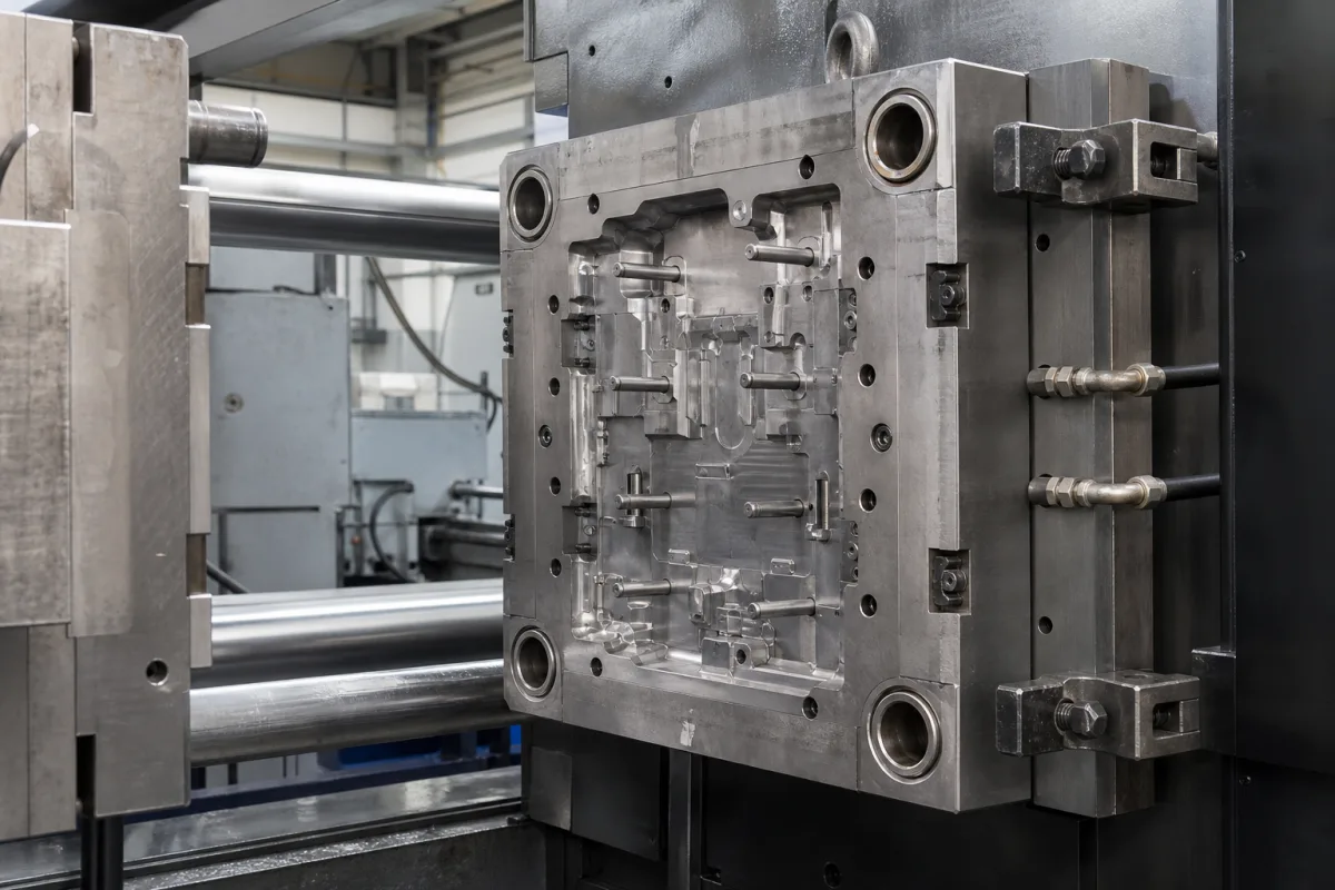
Moving die half (ejector half of a die casting die)
Die casting dies — moving (ejector) half · The half of an aluminium or magnesium die casting die that carries cavity inserts, cores and the ejector system, built from H13 (1.2344) hot-work steel to NADCA #207 grades and hardened to 42–52 HRC
A die casting die closes in two halves: the cover (fixed) half on the injection side and the moving or ejector half on the moving platen, which carries cavity inserts, cores and the ejector pins that push the casting out when the die opens. Ask three things first: which casting, alloy and machine the die is for, which steel grade, certification and heat treatment the inserts need, and how the ejector, guiding and cooling are arranged.
Die casting dies for aluminium, magnesium and zinc high- and low-pressure die casting, focusing on the moving (ejector) half — inserts, cores, ejector plates, pins and sleeves, guide pins and bushings, cooling — and the die steel it is made from. Die casting machines (see high pressure die casting machine), die-cast parts (see aluminum die casting), ejector pins sold alone (see precision casting mold ejector pin), plastic injection moulds and forging dies are outside this page except where compared.
CNFX editorial research · Sources checked October 12, 2026 · 4 sources
Specify the die steel, certification and heat treatment
Finkl's DC data sheet (AISI H13, W.Nr. 1.2344, X40CrMoV5-1) lists tooling for aluminium die casting, cores, sleeves and slides among its uses, and gives its analysis as 0.38 % C, 5.25 % Cr, 1.50 % Mo and 1.00 % V (typ.) [1]. It offers DC Premium, a fine-structure quality for low-pressure die casting qualified as NADCA Grade A, and DC Superior, a remelted fine-structure quality for high-pressure die casting qualified as NADCA Grade B with the highest impact properties; all grades are 100 % ultrasonic tested and can be supplied pre-certified to NADCA Standard #207. Delivered annealed to 229 HBW maximum, it reaches 42 to 52 HRC with standard vacuum hardening. [1]
The data sheet summarises the NADCA-recommended hardening of die casting dies: slow heating, preheat at 650–705 °C (1,200–1,300 °F), harden at 1,025–1,035 °C (1,875–1,895 °F) for 30–45 minutes, quench to 150 °C (300 °F), and temper at 565 °C (1,050 °F) minimum, with double tempering recommended; stress relieving is done 30–55 °C below the final tempering temperature. It lists blocks up to 16,330 kg, 1,270 mm wide and 760 mm thick. [1]
Editorial calculation: the hardening window is only 10 °C wide (1,025–1,035 °C), and the 42–52 HRC range spans 10 HRC points that the heat treater must hit for the specified insert hardness. [1]
Give the supplier the casting drawing and alloy, the die casting machine and platen and tie-bar dimensions, shot weight, the number of cavities, steel grade and NADCA #207 certification, required insert hardness, heat treater and records, cooling layout, ejector layout and stroke, surface treatment, trial shots and acceptance criteria.
02
Plan inserts, ejection and resistance to heat checking
A study recorded by OSTI of AISI H13 for die casting tooling names wrought H13 as the leading US alloy for die casting dies; in thermal fatigue testing, surface hardness fell significantly with thermal cycling and heat checking appeared in as few as 50 cycles, and premium-grade wrought H13 gave the best overall resistance to heat checking, with investment-cast and heat-treated H13 behaving similarly to standard wrought material. [2]
Die size now follows machine size at the top of the market. IDRA lists its Giga Press NEO range at 5,500, 6,100, 8,000 and 9,000 t of clamping force, says these machines already make one-piece automotive body-in-white castings for electric and hybrid vehicles, and that it was first to receive production orders for 9,000 t machines aimed at SUV and small-truck parts. [4] Editorial calculation: 9,000 t is about 88,300 kN; with an assumed metal intensification pressure of 80 MPa, that clamping force holds a projected casting area of about 1.1 m² (about 0.67 m² at 5,500 t), so the moving and fixed die halves, ejector system and inserts must be engineered for that area and force; state the machine, its tie-bar spacing and maximum die height in the die enquiry. [4]
03
Die casting mould makers listed: Minghe and Kingship
Minghe lists die casting mould manufacturing and Kingship lists die casting tooling and mould design; ask each for the steel certificates, heat treatment records and die-life basis below.
Ask any supplier for the die design and flow simulation, steel grade and mill certificates with NADCA #207 test results, heat treatment records and hardness, insert and core layout, ejector design and stroke, cooling and temperature control, surface treatments, die life expectation with its basis, trial and sampling plan, and spare inserts.
04
Set hardness, austenitizing and EDM finishing for thermal fatigue
A US DOE-funded final report from Case Western Reserve University tested Premium Grade H-13 and three other die steels with an immersion thermal fatigue specimen, rating results by average maximum crack length and total crack area, and with Charpy V-notch tests from -100 °F to 450 °F. It found that faster cooling rates in heat treatment give higher thermal fatigue resistance and toughness, and that austenitizing at 1925 °F gives better thermal fatigue resistance than 1875 °F, while 1875 °F gives better toughness. Higher hardness improved thermal fatigue resistance but reduced toughness, and the report states that "A minimum of Rc 46 hardness is desired for aluminum die casting dies." [3]
The report found that EDM reduces thermal fatigue resistance compared with conventional machining, and that using "multiple small steps of decreasing energy and post-EDM treatments" can reduce the effect "to a very slight amount." [3] Editorial calculation: 1875 °F is 1,024 °C and 1925 °F is 1,052 °C, so the higher temperature lies above the 1,025–1,035 °C hardening range in Finkl's data sheet [1]; agree the austenitizing temperature, quench rate, final hardness and EDM finishing steps with the die maker in writing.
05
Cavity inserts, cores and slides, ejector plate and pins, guide pins, die holder and cooling channels
Only the insert and core rows cite a source (Finkl's list of H13 uses and the OSTI heat-checking study); ejector, guide, holder and cooling details come from the die maker's design. [1][2]
Die height, ejector stroke and force, clamping force, insert steel and hardness for a die order
The steel rows can be filled from Finkl's data sheet and the clamping row from IDRA's giga presses; shut height, ejector stroke and force, and guide pin size come only from the die design.
Field
What it means and published values
Ask the supplier for
Die Height (Closed) (mm)
Not stated in the reviewed sources.
Shut height.
Ejector Stroke (mm)
Not stated in the reviewed sources.
Stroke.
Ejector Force (kN)
Not stated in the reviewed sources.
Force.
Clamping Force (kN)
Machine size; e.g. 5,500–9,000 t (about 54,000–88,300 kN) giga presses. [4]
2 companies list this product among what they make. Company figures are quoted from each
company's own website; every card states where the relationship came from.
Minghe Die Casting Company
Manufacturing site to be confirmed for the order
Its website lists die casting mould manufacturing.
Explore company information and manufacturing capabilities, then discuss the scope of your project with a relevant supplier.
Share this page
Compiled and source-reviewed by the CNFX editorial team.
Each manufacturer above links to the page on that company's own website where the product is listed, with the date we checked it. How we source and review
· Page last updated 13 October 2026
Buyer questions
Which steel is used for die casting die inserts?
Finkl offers H13 (1.2344) in grades qualified to NADCA Grade A and B, certifiable to NADCA #207. [1]
How are H13 die casting dies hardened?
Preheat 650–705 °C, harden 1,025–1,035 °C, quench, then double temper at 565 °C minimum. [1]
How soon can heat checking start?
The OSTI study saw heat checking after as few as 50 thermal cycles. [2]
What hardness should an H13 die casting die have?
A Case Western Reserve University report for the US DOE states that a minimum of Rc 46 is desired for aluminium die casting dies, noting that higher hardness improves thermal fatigue resistance but reduces toughness. [3]
How large are the biggest die casting machines that dies are built for?
One maker lists giga presses of 5,500 to 9,000 t clamping force producing one-piece automotive body castings. [4]
Sources and what still needs a direct check
Sources checked 2026-10-12. Finkl Steel makes H13 die steel; the OSTI record is a US national laboratory study of H13 die casting tooling, the Case Western Reserve University report was funded by the US DOE, and IDRA's Giga Press page gives current machine clamping forces.