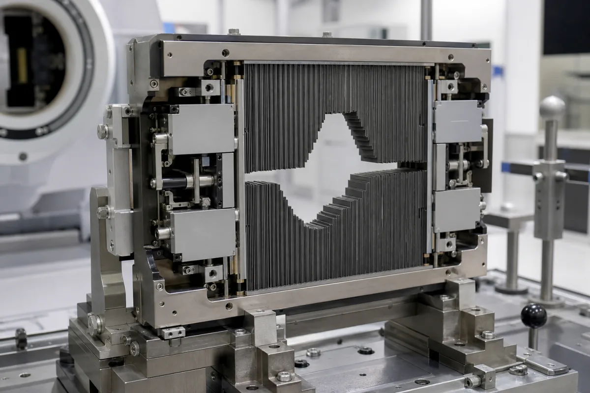
Multileaf collimators for radiotherapy linacs · 20–60 leaf pairs, leaf width at isocentre and micro-MLCs, integral versus add-on mounting, sub-millimetre leaf positioning, transmission and leakage, acceptance, commissioning and QA
A multi-leaf collimator (MLC) is the beam-shaping device in a radiotherapy linear accelerator head: opposing banks of narrow tungsten leaves, each driven by its own motor under computer control, that form irregular field shapes matching the tumour outline and, moving during treatment, modulate beam intensity. Ask three things first: what leaf count and leaf width at isocentre the treatments need, whether it is integral to the linac head or an add-on, and how leaf position, leakage and software links are tested and maintained.
Multileaf collimators and micro-MLCs for medical linear accelerators, integral or add-on. Complete linear accelerators (see medical linear accelerator), fixed secondary jaws, cerrobend blocks and industrial radiography collimators are outside this page.
CNFX editorial research · Sources checked October 12, 2026 · 4 sources
The IAEA handbook Radiation Oncology Physics (2005) describes MLCs with 20 to 60 pairs of narrow, closely abutting tungsten leaves, each projecting a width of 10 mm or less at the linac isocentre; micro-MLCs project less than 5 mm and are used for irregular fields under 10 cm, such as head and neck, or under 3 cm, such as radiosurgery. An MLC may be integral to the linac head, replacing the upper or lower secondary jaws, or attached to the head and used with both sets of jaws. [1]
Each leaf is driven independently by a miniature DC motor under computer control, positioned to better than 1 mm, with a servomechanism using electronic or optical/video sensing to control and verify leaf positions. Beyond static field shaping, MLCs deliver intensity-modulated radiotherapy (IMRT) by multiple static shaped fields or by dynamic leaf motion. [1]
Editorial calculation: 40 leaf pairs at 10 mm projected width cover 40 cm of field length at isocentre, while 60 pairs at 5 mm cover 30 cm; finer leaves shape small targets more closely but cover a shorter field unless the leaf count rises, so match the leaf layout to the largest and smallest fields you treat. [1]
Give the supplier the linac make and model, mounting (integral or add-on), leaf count and projected width at isocentre, maximum field size, leaf travel and over-travel across the central axis, leaf speed, transmission and inter-leaf leakage limits, position-verification method, IMRT and VMAT capability, treatment planning and record-and-verify interfaces, acceptance test protocol and service terms.
02
Plan acceptance, commissioning and QA
The handbook says MLC acceptance testing must cover mechanical aspects (leaf motion and maximum travel, abutting leaves on and off the central axis, alignment with the secondary collimator axes, positional reproducibility, leaf interlocks and jaw tolerances), radiation aspects (leaf transmission, leakage between leaves and at abutting leaf ends, and penumbra along and across the leaves) and software (field shaping, the link from the treatment planning system and controller function). [1]
Commissioning should confirm that the MLC does not appreciably change open-beam flatness, symmetry, collimator, output and scatter factors and percentage depth dose, and ongoing QA should cover positional accuracy, leaf motion reliability, leakage, interlocks, networking and data transfer. In the handbook's sample linac QA programme based on AAPM TG-40, light and radiation field coincidence has a monthly action level of 2 mm or 1% on a side. [1]
Editorial note: agree the leaf-position test method, tolerances and frequency with your physicist before acceptance, and ask the supplier for the leaf-motor replacement procedure and expected service intervals.
Why positioning accuracy matters is quantified in a 2024 study in Reports of Practical Oncology and Radiotherapy by Katayama and co-authors, who added systematic leaf-position errors of ±0.1 to ±1.0 mm per bank (gap changes of ±0.2 to ±2.0 mm) to single-isocentre radiosurgery plans for multiple brain metastases on a 5 mm-leaf Millennium 120 MLC. Target D98% changed by 13.3% per millimetre of MLC error with dynamic conformal arcs and 15.3% per millimetre with VMAT, and the normal-brain V12Gy changed by 47.1% and 53.2% per millimetre. [4] Editorial calculation: at those rates, a systematic 0.5 mm error shifts target coverage by about 7–8% and the normal-brain V12Gy by about 24–27%, so agree with your physicist whether the 1 mm positioning figure above is tight enough for radiosurgery. [4][1]
03
Check delivery features and the device class of the linac
Elekta describes the high-definition dynamic radiosurgery (HDRS) sequencing on its Versa HD linac as optimising the jaws across the full 40 cm field, using 1,024 dynamic control points and a 1 mm virtual leaf width, with low leakage through the leaves and jaws while delivering in flattening-filter-free high dose-rate mode; it states that SBRT and SRS treatments can be delivered in a standard 15-minute slot. [2]
In the United States the MLC is a component of a medical charged-particle radiation therapy system, which 21 CFR 892.5050 classifies as Class II, covering component parts and accessories along with planning software and patient supports; an add-on MLC is therefore cleared with or for the linac it fits. [3]
Editorial calculation: a 1 mm virtual leaf width across a 40 cm field gives 400 ÷ 1 = 400 steps across the field, against 400 ÷ 5 = 80 for physical 5 mm leaves, so ask how the virtual width is produced and verified in QA. [2][1]
04
Two linac makers with 120-leaf MLCs built in
United Imaging (uRT-linac 506c) and Shinva (XHA600E) each list a linac with an integrated 120-leaf MLC; neither sells the MLC separately, so an add-on MLC for another linac is not offered here.
05
Leaves, motors, position sensing, carriage, controller and interlocks
All six parts are named in the IAEA handbook; the third column lists what each maker must state for its own collimator.
Leaf pairs, width, accuracy, leakage and QA values for the quotation
Field sizes and techniques come from your clinic. The middle column holds IAEA handbook figures and the Katayama error study, not values from a product data sheet.
2 companies list this product among what they make. Company figures are quoted from each
company's own website; every card states where the relationship came from.
Shanghai United Imaging Medical Technology Co., Ltd.
Manufacturing site to be confirmed for the order
Its website lists the uRT-linac 506c medical linear accelerator with an integrated 120-leaf dynamic MLC (5 mm minimum leaf width at isocenter, 6.5 cm/s leaf speed); the MLC is listed as part of the accelerator, not sold separately.
Its website lists the XHA600E medical linear accelerator with an integrated high-speed dynamic MLC with 120 leaves; the MLC is listed as part of the accelerator, not sold separately.
Explore company information and manufacturing capabilities, then discuss the scope of your project with a relevant supplier.
Share this page
Compiled and source-reviewed by the CNFX editorial team.
Each manufacturer above links to the page on that company's own website where the product is listed, with the date we checked it. How we source and review
· Page last updated 13 October 2026
Buyer questions
How many leaves does an MLC have?
The IAEA handbook describes 20 to 60 pairs of tungsten leaves. [1]
What is a micro-MLC?
An MLC whose leaves project less than 5 mm at isocentre, used for small fields such as head and neck and radiosurgery. [1]
What does MLC acceptance testing cover?
Mechanical motion and alignment, radiation transmission and leakage, and the software link to planning and control. [1]
What regulatory class covers an MLC in the US?
It falls under the medical charged-particle radiation therapy system, which 21 CFR 892.5050 classifies as Class II with its component parts and accessories. [3]
How much does a small MLC leaf error change radiosurgery dose?
One planning study found target D98% changed by 13–15% and normal-brain V12Gy by 47–53% per millimetre of systematic MLC error in multi-metastasis radiosurgery. [4]
Sources and what still needs a direct check
Sources checked 2026-10-12. The IAEA handbook (2005) is a teaching text on radiotherapy physics; it is not a product specification. Values for your MLC must come from the manufacturer and your physicist's acceptance tests.