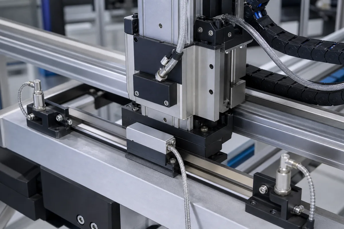
Magnetostrictive linear position sensor (rod and profile types)
Magnetostrictive linear position sensors · rod and profile housings, null and dead zone, waveguide time of flight, multiple magnets
A magnetostrictive linear position sensor measures the absolute distance between a non-contact position magnet and the head of a sensing rod, by timing a torsional strain pulse travelling along a ferromagnetic waveguide. It is built as a rod that fits inside a hydraulic cylinder or as a profile housing bolted along a machine axis such as a gantry. Ask three things first: the stroke and the length the rod needs beyond it, whether the sensor goes in a cylinder or on a profile, and which output and how many magnets it must read.
Magnetostrictive (waveguide time-of-flight) linear position sensors in rod, two-piece cylinder and profile housings, with their position magnets and electronics heads, specified by stroke, null and dead zone, output interface, supply and number of magnets. Optical and magnetic scale linear encoders with incremental read heads are covered on the Linear encoder page. Inductive limit and home switches, LVDTs, potentiometers, ultrasonic sensors and magnetostrictive liquid level gauges are outside this page except where compared.
CNFX editorial research · Sources checked October 12, 2026 · 3 sources
Size the sensing rod from stroke, null and dead zone
Design World's guide to magnetostrictive sensors explains that the sensor measures the distance between a position magnet and the head end of the sensing rod, and that strokes run from as short as 25 mm to as long as 10 m. The rod is longer than the stroke: a minimum distance called the null must be kept between the head end and the magnet, and an unusable dead zone at the rod tip. In its example the null is 12 mm and the dead zone 82 mm, so a two-metre travel needs a rod of L = 0.012 m + 2 m + 0.082 m = 2.094 m. [1]
The same guide describes two cylinder-mounting options, standard and two-piece, both with rods and flanges that seal against cylinder pressure, and a profile housing in which the sensing rod is enclosed in an aluminium extrusion bolted to the machine frame. In the profile version the magnet can be a bar or floating magnet passing near the top of the extrusion, or captive in a shuttle riding on a rail in the extrusion; a clevis-mounted rod and cylinder version moves the magnet with a metal rod. [1]
The magnet can be read through a barrier of non-magnetic material, such as a cylinder wall, and some sensor models accept up to 30 position magnets on one rod, so one sensor can read more than one carriage on the same axis; the guide's example is a paper slitter with one magnet per knife. [1]
Editorial note: null and dead zone lengths depend on the model and mounting; ask the supplier for both figures for the housing you order before fixing the axis layout.
Send the travel to be measured, available length for the rod or profile, cylinder or frame mounting, number of magnets, magnet type (ring, floating, captive), output interface and update rate, supply voltage, temperature, shock and vibration, and enclosure needs.
02
Understand the waveguide timing behind the reading
A Chinese patent on a high-measuring-frequency magnetostrictive sensor, CN 104457809 A, describes the Wiedemann effect: an interrogation pulse sent along the waveguide wire meets the field of the magnet ring and forms a torsional stress wave, whose return is timed; multiplying the time difference by the wave's propagation speed in the waveguide material, about 2,830 m/s, gives the absolute distance from the reference point. [2] Editorial calculation: at 2,830 m/s the wave covers 1 m in about 0.35 ms.
The same patent states that because the returning torsional wave is slow compared with the excitation pulse, the measuring frequency of a single measuring unit is limited; it proposes n ≥ 2 measuring units taking turns so that the highest measuring frequency becomes k times that of the original design, and singles out sensors with ranges over 1 m as where the gain is largest. [2]
SICK Atech GmbH's patent US 11,713,981 B2, for an evaluation unit, describes the magnetostrictive element as a thin rod, wire or tube of a ferromagnetic material such as iron, nickel or cobalt, from a few centimetres to metres long, with a ring-shaped permanent position magnet around it. It uses a reference signal time of flight so that length changes or speed-of-sound changes in the element caused by temperature can be compensated. [3]
Design World lists 24 Vdc as the standard supply for industrial sensors, with 15 Vdc on older systems and a 9–28.8 Vdc extended option; analog outputs of 0–20 mA, 4–20 mA or −10 to 10 V; and SSI, CANbus, DeviceNet, Profibus, EtherCAT or PowerLink digital interfaces, with SSI and EtherCAT cited for a 10 kHz update rate. [1]
03
Compare housing types
The housings below come from the sources reviewed; each fixes how the magnet and rod are mounted.
Housing
How it mounts
Ask the supplier for
Rod, standard
Threads into a cylinder end cap; rod runs in a hollow piston rod. [1]
Pressure rating, thread, flange.
Rod, two-piece
Sensing element and head withdraw without venting cylinder pressure. [1]
Replacement procedure.
Profile, floating magnet
Aluminium extrusion on the frame; magnet passes near the top. [1]
Allowed gap and offset.
Profile, captive shuttle
Magnet in a shuttle on a rail in the extrusion. [1]
Yumo lists magnetostrictive sensor series with analog, Modbus, SSI or CAN bus outputs; ask for the null, dead zone and linearity of the series offered.
YUEQING YUMO ELECTRIC CO.,LTD
Manufacturing site to be confirmed for the order
Lists MT, MHA, MI, MH, ES, EP, EJ, HP and ESC series magnetostrictive linear position sensors with analog, Modbus, SSI or CAN bus outputs.
Explore company information and manufacturing capabilities, then discuss the scope of your project with a relevant supplier.
Share this page
Compiled and source-reviewed by the CNFX editorial team.
Each manufacturer above links to the page on that company's own website where the product is listed, with the date we checked it. How we source and review
· Page last updated 13 October 2026
Buyer questions
How long must the rod be for a given stroke?
Stroke plus null plus dead zone. Design World's example uses a 12 mm null and 82 mm dead zone, giving 2.094 m for a 2 m stroke. [1]
Can one magnetostrictive sensor read more than one position?
Yes. Design World states that some models accept up to 30 position magnets on one sensing rod. [1]
How does the sensor find the magnet?
CN 104457809 A describes timing a torsional wave raised by the Wiedemann effect, travelling at about 2,830 m/s in the waveguide. [2]
Sources and what still needs a direct check
Sources checked 2026-10-12. Design World is an engineering trade publication; its guide draws on Temposonics sensors. The two patents describe the waveguide principle and signal evaluation as stated by their applicants (SICK Atech GmbH and an individual Chinese inventor).