Editorial Technical Reference

Orientation Track/Selector

This page explains how Orientation Track/Selector is classified within Machinery and Equipment Manufacturing. Technical values and manufacturer relationships are research references; confirm the current specification and supplier evidence for each order.

Technical Definition & Core Assembly

A mechanical component within a cap feeding system that orients and selects caps into the correct position for downstream processes.
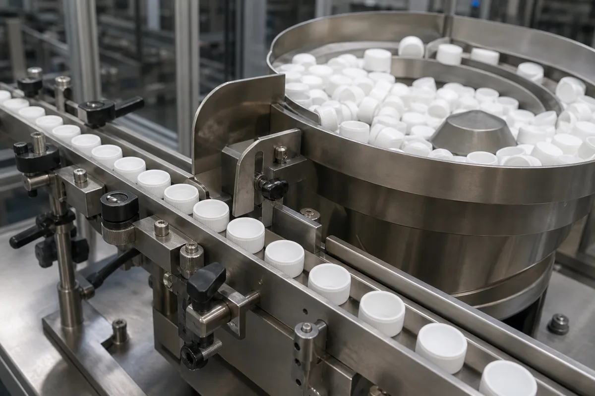
Orientation Track/Selector in a manufacturing environment
Representative product image. Confirm appearance and specifications with the manufacturer.

Product Specifications

Technical details and manufacturing context for Orientation Track/Selector

Definition
The Orientation Track/Selector is a critical component of automated cap feeding systems used in packaging lines. It receives randomly oriented caps from a hopper or feeder and systematically reorients them into a uniform, predetermined position (typically upright with the open side facing down) before transferring them to capping stations. This ensures proper cap placement and sealing during container filling operations. The component is designed for integration into existing packaging machinery, with a rated capacity of 50–200 pieces per minute depending on cap size and track length. It accommodates cap diameters from 15 to 60 mm and cap heights from 10 to 40 mm, with an orientation accuracy of ±0.5 degrees. Operating pressure ranges from 0.4 to 0.6 MPa, and air consumption is 0.1–0.3 m³/min at rated conditions. The device operates in non-condensing environments from 0 to 50 °C and offers ingress protection ratings of IP54 to IP65 (IEC 60529), with IP65 suitable for washdown environments. Standard materials include stainless steel (AISI 304/316), anodized aluminum, and engineering plastics such as UHMW-PE and acetal. The unit weighs 15–30 kg depending on configuration, with typical dimensions of 800×400×600 mm (L×W×H). These values are reference ranges for standard models; actual specifications must be confirmed with the legal manufacturer or supplier for specific applications. The Orientation Track/Selector is a component, not a standalone machine, and its performance depends on proper integration with upstream feeding and downstream capping equipment. Verification of compatibility, including cap geometry and track adjustments, is essential. Maintenance signals include increased misfeeds, jams, or orientation errors, which may indicate wear on rails or gates. Failure boundaries are limited to the component itself; it does not include the hopper, feeder, or capping station. Always consult the manufacturer for model-specific data and standards compliance.
Working Principle
Caps are fed into the track via vibration or gravity. As they travel along the track's guided path, specially designed rails, grooves, or mechanical gates interact with the caps' geometry (e.g., threads, skirts, or specific profiles). Caps in the incorrect orientation are rejected back into the feed system or diverted, while correctly oriented caps continue along the track to the discharge point for transfer to the capping mechanism. The selection process relies on physical interaction, not sensors or electronic controls, ensuring reliable operation in industrial environments. The track's design must match the cap's dimensions and profile; deviations outside the specified ranges may require custom tooling. Proper adjustment of vibration amplitude, track angle, and gate timing is critical for consistent performance. Regular inspection of wear parts, such as rails and gates, is necessary to maintain orientation accuracy. The system operates within defined pressure and temperature limits; exceeding these may cause misfeeds or damage. For applications requiring food-grade materials, optional stainless steel grades are available, but certification must be verified with the supplier.
Common Materials
Stainless Steel (AISI 304/316), Anodized Aluminum, Engineering Plastics (e.g., UHMW-PE, Acetal)
Technical Parameters
ParameterTypical rangeNotes & selection driver
Rated Capacity50–200 pcs/minDepends on cap size and track length
Cap Diameter Range15–60 mmOutside range requires custom tooling
Cap Height Range10–40 mmFor standard models
Orientation Accuracy±0.5 °Angular deviation of cap orientation
Operating Pressure0.4–0.6 MPaBelow 0.4 MPa may cause misfeeds
Air Consumption0.1–0.3 m³/minAt rated pressure and capacity
Operating Temperature0–50 °CNon-condensing environment
Ingress ProtectionIP54–IP65IP65 for washdown environmentsIEC 60529
Material304 SSFood-grade optionalASTM A240
Weight15–30 kgDepends on configuration
Dimensions (L×W×H)800×400×600 mmTypical for mid-range model

Ranges are indicative industry figures for RFQ preparation, not a supplier commitment. Confirm every value and standard with the legal manufacturer before ordering.

Components / BOM
  • Guide Rails Part
    Direct the cap's path and physically interact with its features to induce rotation or rejection based on orientation.
    Material: Stainless Steel or UHMW-PE
  • Rejection Gate/Mechanism
    Diverts or returns incorrectly oriented caps to the feed hopper for recirculation.
    Material: Stainless Steel or Aluminum
  • Track Base/Frame
    Provides structural support and mounting points for the entire orientation assembly.
    Material: Anodized Aluminum or Powder-Coated Steel

Applied To / Applications

This component is essential for the following industrial systems and equipment:

Industrial Ecosystem & Supply Chain Structure

Complementary Systems
Downstream Applications
Specialized Tooling

Application Fit & Sizing Matrix

Operational Limits
pressure: Atmospheric to 2 bar
flow rate: Up to 500 caps/min
temperature: -10°C to 80°C
slurry concentration: Not applicable (dry handling component)
Media Compatibility
✓ Plastic caps (HDPE, PP) ✓ Metal caps (aluminum, steel) ✓ Glass caps
Unsuitable: High-viscosity liquid-filled caps or caps with external adhesives
Sizing Data Required
  • Cap diameter range (mm)
  • Cap height range (mm)
  • Required throughput (caps/min)

Reliability & Engineering Risk Analysis

Failure Mode & Root Cause
Track Misalignment
Cause: Improper installation, foundation settling, or excessive load causing uneven wear and binding.
Selector Mechanism Jamming
Cause: Contamination ingress (dust, debris), lack of lubrication, or mechanical wear in linkage components.
Maintenance Indicators
  • Audible grinding or scraping noises during operation
  • Visible uneven wear patterns or scoring on track surfaces
Engineering Tips
  • Implement regular laser alignment checks and precision leveling during installation to prevent premature wear
  • Establish a preventive lubrication schedule with appropriate grease types and install protective seals to minimize contamination

Indicative industry ranges for design and RFQ preparation. Confirm the exact figures and applicable standard with the manufacturer before specifying.

Compliance & Manufacturing Standards

Applicable Standards
ANSI B11.19 Performance Criteria for Safeguarding CE Marking (Machinery Directive 2006/42/EC)

Quoted from the published standard.

Manufacturing Precision
  • Bore Diameter: +/-0.01mm
  • Parallelism: 0.05mm per 100mm length
Quality Inspection
  • Coordinate Measuring Machine (CMM) Verification
  • Functional Load Testing with Torque Measurement

Manufacturers of Orientation Track/Selector

Manufacturer profiles associated with Orientation Track/Selector.

Sourcing Orientation Track/Selector from China?
Tell us your specification and target quantity — we will match it against manufacturer records and come back with the factories that fit.
Request manufacturers We manufacture this

Manufacturer listings support early research and capability understanding. They are not certification, ranking, or transaction guarantees.

Share this page
Technical documentation
Request current drawings, revision history, and a signed specification sheet.
Manufacturing capability
Verify equipment lists, process limits, capacity, and representative production evidence.
Inspection readiness
Confirm test methods, calibrated equipment, sampling plans, and traceable reports.
Supplier transparency
Check the legal entity, factory address, ownership, certifications, and direct contacts.

CNFX does not score or rank suppliers. Buyers must verify all claims and documents with the legal manufacturer before ordering.

Supply Chain Compatible Machinery & Devices

Heavy-Duty CNC Plasma Cutting Machine

The Heavy-Duty CNC Plasma Cutting Machine is a standalone industrial device designed for cutting conductive metals such as steel, stainless steel, aluminum, and copper alloys.

Explore Specs →
Automated Powder Coating System

Integrated industrial system for applying dry powder coatings to metal substrates.

Explore Specs →
Centrifugal Pump Impeller

The centrifugal pump impeller is a critical rotating component that converts mechanical energy from the motor into kinetic energy in fluid systems.

Explore Specs →
High-Precision CNC Laser Cutting Machine

Computer-controlled industrial machine using focused laser beams to cut sheet metal with micron-level accuracy.

Explore Specs →

Frequently Asked Questions

What is the typical capacity range of the Orientation Track/Selector?

The rated capacity is 50–200 pieces per minute, depending on cap size and track length. This is a reference range for standard models; actual capacity must be confirmed with the manufacturer for your specific cap dimensions and configuration.

Which cap sizes can this component handle?

It handles cap diameters from 15 to 60 mm and cap heights from 10 to 40 mm. Outside these ranges, custom tooling may be required. Always verify compatibility with your cap geometry before integration.

What materials are used in construction?

Standard materials include stainless steel (AISI 304/316), anodized aluminum, and engineering plastics such as UHMW-PE and acetal. Food-grade options may be available, but certification must be verified with the supplier.

What maintenance is required?

Regular inspection of rails, grooves, and gates for wear is recommended. Increased misfeeds or orientation errors may indicate wear or misalignment. Ensure operating pressure and temperature remain within specified limits to avoid malfunctions.

Data Basis

Editorial classification, named public sources where available, and source-reviewed manufacturer records.

Preliminary Technical Classification
This page supports structured research, RFQ preparation, and supplier evaluation. It does not replace buyer-led supplier qualification, standards review, or technical approval.
Buyer enquiry

Request manufacturing insight for Orientation Track/Selector

Ask for use case, specification boundaries, supplier type, and RFQ preparation information for this product.

Where it goes
Straight to the CNFX editorial desk, and to the manufacturer if this product is linked to a claimed profile. Nothing is broadcast to a supplier list.
Your details stay here
We do not sell or rent enquiry data, and we do not add you to a mailing list. Used only to answer this request.
No commission, no middleman
CNFX is a directory. We take no cut of any order and never negotiate on a supplier's behalf.
What we don't claim
A listing is not an endorsement. Qualify every supplier and verify every figure yourself before ordering.

Your business information is used only to process this request.

Thank you! Your message has been sent. We'll respond within 1–3 business days.
Sorry, we couldn't send your message. Please try again, or email us at [email protected].

Need to Manufacture Orientation Track/Selector?

Compare manufacturer profiles with relevant product and process capability.

Previous Product
Z-axis Ram/Spindle
Last Product
Get QuotesChat