Editorial Technical Reference

Orientation/Selection Track

This page explains how Orientation/Selection Track is classified within Machinery and Equipment Manufacturing. Technical values and manufacturer relationships are research references; confirm the current specification and supplier evidence for each order.

Technical Definition & Core Assembly

A mechanical track within a terminal feeding system that guides, orients, and selects components or products for proper positioning and routing.
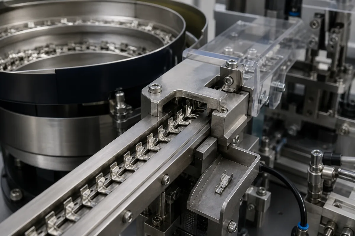
Representative product image. Confirm appearance and specifications with the manufacturer.

Product Specifications

Technical details and manufacturing context for Orientation/Selection Track

Definition
The Orientation/Selection Track is a critical component of the Terminal Feeding System, responsible for receiving components or products from upstream processes and ensuring they are correctly oriented and selected for subsequent assembly, packaging, or processing stages. It utilizes mechanical guides, sensors, and sometimes actuators to align items, reject incorrectly positioned ones, and direct them onto the correct path. The track is designed to handle a range of component sizes, with track widths from 10 to 200 mm and lengths from 500 to 3000 mm, accommodating various production line configurations. Orientation accuracy is maintained within ±0.1 mm, ensuring precise placement for downstream operations. Feed rates can vary from 0.5 to 2.0 m/s, with higher speeds potentially reducing accuracy, so the system must be tuned for the specific application. The track operates within a temperature range of -10 to 60 °C, and its maximum load capacity is 50 to 500 kg, beyond which deformation may occur. Materials commonly used include stainless steel, aluminum alloy, and engineering plastics such as UHMW-PE or Acetal, with material hardness ranging from 40 to 60 HRC for wear resistance. Surface roughness is specified as Ra 0.8 to 1.6 µm to reduce friction and wear. Drive power requirements depend on track length and load, typically 0.25 to 2.2 kW. The system requires a 24 V DC supply voltage (±10%) for sensors and actuators, and is rated IP54 to IP65 for protection against dust and water. The track's weight ranges from 50 to 300 kg, affecting installation and support structure. All values are reference ranges and must be verified for the specific model and application with the legal manufacturer or supplier.
Working Principle
Components enter the track from a feeder or conveyor. The track's geometry (rails, guides, grooves) physically constrains and reorients items as they move. Integrated sensors (e.g., optical, proximity) detect orientation, presence, or specific features. Based on sensor input, a selection mechanism (e.g., a diverter gate, pusher, or reject arm) is activated to route correctly oriented items forward and eject or redirect misaligned or defective items. The system operates within specified feed rates and accuracy limits, and its performance is influenced by track width, length, and material properties. Regular inspection of sensors and mechanical parts is necessary to maintain orientation accuracy and prevent jams or misrouting.
Common Materials
Stainless Steel, Aluminum Alloy, Engineering Plastic (e.g., UHMW-PE, Acetal)
Technical Parameters
ParameterTypical rangeNotes & selection driver
Track Width10–200 mmDetermines component size compatibility
Track Length500–3000 mmAffects orientation time and throughput
Orientation Accuracy±0.1 mmCritical for precise placement
Feed Rate0.5–2.0 m/sHigher speeds may reduce accuracy
Operating Temperature-10–60 °COutside range may affect material properties
Max Load Capacity50–500 kgExceeding may cause deformation
Material Hardness40–60 HRCWear resistance for abrasive parts
Surface RoughnessRa 0.8–1.6 µmSmoother reduces friction and wear
Drive Power0.25–2.2 kWDepends on track length and load
Supply Voltage24 ±10% V DCFor sensors and actuators
IP RatingIP54–IP65Protection against dust and waterIEC 60529
Weight50–300 kgAffects installation and support structure

Ranges are indicative industry figures for RFQ preparation, not a supplier commitment. Confirm every value and standard with the legal manufacturer before ordering.

Components / BOM
  • Guide Rails Part
    Physically constrain and guide the component along a defined path, initiating the orientation process.
    Material: Stainless Steel or Aluminum
  • Sensor Mounting Bracket Part
    Holds orientation detection sensors (e.g., photoelectric, vision) in precise positions along the track.
    Material: Aluminum Alloy
  • Diverter Gate/Reject Mechanism
    Actuated component (pneumatic, electric) that physically redirects or ejects components based on the selection logic.
    Material: Stainless Steel, Engineering Plastic
  • Track Base/Frame
    Provides structural support and mounting points for all other track components, ensuring alignment and rigidity.
    Material: Aluminum Profile or Steel
  • Orientation Sensors
    Detect each part's orientation and tell the diverter whether to pass or reject it.

Industry Taxonomies & Aliases

Commonly used trade names and technical identifiers for Orientation/Selection Track.

Applied To / Applications

This component is essential for the following industrial systems and equipment:

Industrial Ecosystem & Supply Chain Structure

Complementary Systems
Downstream Applications
Specialized Tooling

Application Fit & Sizing Matrix

Operational Limits
pressure: Atmospheric to 0.5 bar gauge
other spec: Component size: 5-100 mm, Max flow rate: 5000 units/hour, Max slurry concentration: 10% solids by weight
temperature: -20°C to 80°C
Media Compatibility
✓ Plastic pellets ✓ Metal fasteners ✓ Pharmaceutical capsules
Unsuitable: Highly abrasive slurries with >10% solids concentration
Sizing Data Required
  • Component dimensions (LxWxH)
  • Required throughput (units/hour)
  • Orientation accuracy requirement (± degrees)

Reliability & Engineering Risk Analysis

Failure Mode & Root Cause
Bearing fatigue failure
Cause: Improper alignment or excessive radial/axial loads during installation, leading to premature bearing wear and eventual seizure.
Shaft misalignment-induced vibration
Cause: Incorrect mounting or thermal expansion mismatches causing excessive vibration, leading to seal damage and component fatigue.
Maintenance Indicators
  • Unusual high-frequency whining or grinding noise during operation
  • Visible wobble or irregular motion of the track assembly during rotation
Engineering Tips
  • Implement laser alignment during installation and periodic realignment checks to ensure proper shaft and bearing alignment.
  • Establish vibration monitoring with baseline readings and trend analysis to detect early misalignment or bearing degradation.

Indicative industry ranges for design and RFQ preparation. Confirm the exact figures and applicable standard with the manufacturer before specifying.

Compliance & Manufacturing Standards

Applicable Standards
ANSI/ASME B46.1-2019 (Surface Texture)

Quoted from the published standard.

Manufacturing Precision
  • Bore Diameter: +/-0.01mm
  • Parallelism: 0.05mm per 100mm length
Quality Inspection
  • Dimensional Verification with CMM (Coordinate Measuring Machine)
  • Hardness Testing (Rockwell C Scale)

Manufacturers of Orientation/Selection Track

Manufacturer profiles associated with Orientation/Selection Track.

Sourcing Orientation/Selection Track from China?
Tell us your specification and target quantity — we will match it against manufacturer records and come back with the factories that fit.
Request manufacturers We manufacture this

Manufacturer listings support early research and capability understanding. They are not certification, ranking, or transaction guarantees.

Technical documentation
Request current drawings, revision history, and a signed specification sheet.
Manufacturing capability
Verify equipment lists, process limits, capacity, and representative production evidence.
Inspection readiness
Confirm test methods, calibrated equipment, sampling plans, and traceable reports.
Supplier transparency
Check the legal entity, factory address, ownership, certifications, and direct contacts.

CNFX does not score or rank suppliers. Buyers must verify all claims and documents with the legal manufacturer before ordering.

Supply Chain Compatible Machinery & Devices

Automated Powder Coating System

Integrated industrial system for applying dry powder coatings to metal substrates.

Explore Specs →
Centrifugal Pump Impeller

The centrifugal pump impeller is a critical rotating component that converts mechanical energy from the motor into kinetic energy in fluid systems.

Explore Specs →
High-Precision CNC Laser Cutting Machine

Computer-controlled industrial machine using focused laser beams to cut sheet metal with micron-level accuracy.

Explore Specs →
Industrial-Grade Hydraulic Cylinder Piston Rod

This industrial-grade piston rod is a precision-ground cylindrical component designed for use in hydraulic cylinders.

Explore Specs →

Frequently Asked Questions

What is the typical track width range for this component?

The track width is typically 10 to 200 mm, which determines component size compatibility. The exact width must be selected based on the dimensions of the components to be handled.

How does the orientation accuracy affect the system?

Orientation accuracy is specified as ±0.1 mm, which is critical for precise placement in downstream operations. If the accuracy is not maintained, components may be misaligned, to assembly errors or jams.

What materials are commonly used for the track?

Common materials include stainless steel, aluminum alloy, and engineering plastics such as UHMW-PE or Acetal. The choice depends on factors like wear resistance, weight, and cost, and should be verified with the manufacturer.

What is the operating temperature range?

The operating temperature range is -10 to 60 °C. Operating outside this range may affect material properties and performance, so it is important to ensure the environment is within these limits.

Data Basis

Editorial classification, named public sources where available, and source-reviewed manufacturer records.

Preliminary Technical Classification
This page supports structured research, RFQ preparation, and supplier evaluation. It does not replace buyer-led supplier qualification, standards review, or technical approval.
Buyer enquiry

Request manufacturing insight for Orientation/Selection Track

Ask for use case, specification boundaries, supplier type, and RFQ preparation information for this product.

Where it goes
Straight to the CNFX editorial desk, and to the manufacturer if this product is linked to a claimed profile. Nothing is broadcast to a supplier list.
Your details stay here
We do not sell or rent enquiry data, and we do not add you to a mailing list. Used only to answer this request.
No commission, no middleman
CNFX is a directory. We take no cut of any order and never negotiate on a supplier's behalf.
What we don't claim
A listing is not an endorsement. Qualify every supplier and verify every figure yourself before ordering.

Your business information is used only to process this request.

Thank you! Your message has been sent. We'll respond within 1–3 business days.
Sorry, we couldn't send your message. Please try again, or email us at contact@cnfx.com.

Need to Manufacture Orientation/Selection Track?

Compare manufacturer profiles with relevant product and process capability.

Previous Product
Z-axis Ram/Spindle
Last Product
Get QuotesChat