Editorial Technical Reference

Overhead Lifting Mechanism

This page explains how Overhead Lifting Mechanism is classified within Machinery and Equipment Manufacturing. Technical values and manufacturer relationships are research references; confirm the current specification and supplier evidence for each order.

Technical Definition & Core Assembly

A mechanical system designed to vertically lift and position components within an industrial station.
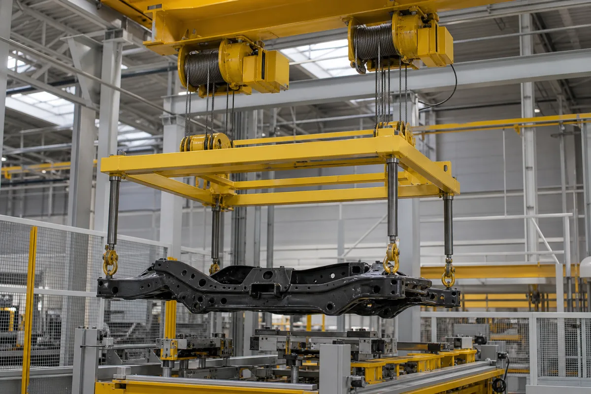
Overhead Lifting Mechanism in a manufacturing environment
Representative product image. Confirm appearance and specifications with the manufacturer.

Product Specifications

Technical details and manufacturing context for Overhead Lifting Mechanism

Definition
The overhead lifting mechanism is a component used in industrial stations, particularly in the Body Drop Station of automotive assembly lines. Its primary function is to raise and lower vehicle bodies or other heavy components with precision during assembly or transfer operations. The mechanism ensures controlled vertical movement and accurate positioning, which is critical for maintaining production line efficiency and product quality.

Constructed from structural steel and alloy steel, the mechanism is designed to withstand demanding industrial environments. It offers a lifting capacity ranging from 5 to 50 kN, a stroke length of 100 to 500 mm, and a lifting speed of 10 to 50 mm/s. Positioning accuracy is ±0.05 mm, ensuring repeatable placement. The operating pressure is 1.0 to 1.6 MPa, with a note that below 1.0 MPa the load may be insufficient. For electric actuation, the supply voltage is 24 V DC ±10%. Power consumption varies between 0.5 and 2.0 kW, depending on load and speed. The mechanism operates in a non-condensing environment within a temperature range of -40°C to 85°C. It has an ingress protection rating of IP54 to IP65, making it dust-tight and water-resistant. The material grade for high-strength steel parts is 45# per GB/T 699. The weight of the mechanism ranges from 50 to 200 kg, depending on capacity and stroke.

This component is typically integrated into a larger system, and its performance must be verified against the specific application requirements. The listed parameters are reference ranges; actual values must be confirmed with the manufacturer or supplier for the specific model. Standards such as IEC 60529 for ingress protection are referenced for verification, but do not imply certification. Always consult the legal manufacturer for detailed specifications and compliance.
Working Principle
The overhead lifting mechanism generates vertical force using hydraulic cylinders, electric actuators, or pneumatic systems. It is mounted overhead and connects to lifting arms or platforms that engage with the load. Control systems regulate the speed, height, and synchronization of the lift, ensuring precise positioning. The mechanism operates within defined parameters, such as lifting capacity and stroke length, and must be selected based on the load and application requirements.
Common Materials
Structural steel, Alloy steel
Technical Parameters
ParameterTypical rangeNotes & selection driver
Lifting Capacity5–50 kNMaximum load at rated pressure
Stroke Length100–500 mmVertical travel range
Operating Pressure1.0–1.6 MPa
Lifting Speed10–50 mm/sNo-load to full-load speed variation
Positioning Accuracy±0.05 mmRepeatability at rated load
Supply Voltage24 ±10% V DCFor electric actuation
Power Consumption0.5–2.0 kWDepends on load and speed
Operating Temperature-40–85 °CNon-condensing environment
Ingress ProtectionIP54–IP65Dust-tight and water-resistantIEC 60529
Material Grade45#High-strength steel for structural partsGB/T 699
Weight50–200 kgVaries with capacity and stroke

Ranges are indicative industry figures for RFQ preparation, not a supplier commitment. Confirm every value and standard with the legal manufacturer before ordering.

Components / BOM
  • Lifting cylinder
    Provides the primary vertical force for lifting operations
    Material: Steel alloy
  • Guide rails Part
    Ensures straight, stable vertical movement without deviation
    Material: Hardened steel
  • Lifting platform/arms Part
    Interface component that directly engages with and supports the load
    Material: Structural steel
  • Control System
    Sets lift speed and height, and keeps multiple lifting points moving together.

Applied To / Applications

This component is essential for the following industrial systems and equipment:

Industrial Ecosystem & Supply Chain Structure

Complementary Systems
Downstream Applications
Specialized Tooling

Application Fit & Sizing Matrix

Operational Limits
pressure: Ambient atmospheric pressure only
other spec: Max Load Capacity: 5000 kg, Lift Speed: 0.1-1.0 m/s, Duty Cycle: 30% max continuous operation
temperature: -20°C to 80°C
Media Compatibility
✓ General manufacturing components ✓ Assembly line parts ✓ Packaged industrial goods
Unsuitable: Corrosive chemical environments or explosive atmospheres
Sizing Data Required
  • Maximum load weight (kg)
  • Required lift height (m)
  • Desired lifting speed (m/s)

Reliability & Engineering Risk Analysis

Failure Mode & Root Cause
Wire rope degradation
Cause: Fatigue from cyclic loading, corrosion from environmental exposure, or abrasion against sheaves and drums leading to broken wires, reduced diameter, or loss of core lubrication.
Bearing seizure in hoist or trolley
Cause: Inadequate lubrication, contamination by dust or moisture, misalignment, or excessive loading causing overheating, increased friction, and eventual lock-up.
Maintenance Indicators
  • Audible grinding, clicking, or irregular noises during operation indicating mechanical wear or misalignment.
  • Visible deformation, cracking, or excessive wear on hooks, sheaves, or structural components, especially at stress points.
Engineering Tips
  • Implement a routine lubrication schedule using manufacturer-specified greases for wire ropes, bearings, and gears, and conduct periodic non-destructive testing (e.g., magnetic particle inspection) on critical load-bearing parts.
  • Install load monitoring sensors and limit switches to prevent overloads, and ensure regular alignment checks and balancing of moving components to reduce uneven wear.

Indicative industry ranges for design and RFQ preparation. Confirm the exact figures and applicable standard with the manufacturer before specifying.

Compliance & Manufacturing Standards

Applicable Standards
ISO 12480-1: Cranes - Safe use - Part 1: General ANSI/ASME B30.2: Overhead and Gantry Cranes DIN 15020: Cranes; principles relating to rope drives; calculation and construction

Quoted from the published standard.

Manufacturing Precision
  • Shaft alignment: +/-0.05mm per meter
  • Gear tooth profile: AGMA Quality 10 tolerance
Quality Inspection
  • Non-destructive testing (NDT) for welds and critical components
  • Load testing to 125% of rated capacity

Manufacturers of Overhead Lifting Mechanism

Manufacturer profiles associated with Overhead Lifting Mechanism.

Sourcing Overhead Lifting Mechanism from China?
Tell us your specification and target quantity — we will match it against manufacturer records and come back with the factories that fit.
Request manufacturers We manufacture this

Manufacturer listings support early research and capability understanding. They are not certification, ranking, or transaction guarantees.

Share this page
Technical documentation
Request current drawings, revision history, and a signed specification sheet.
Manufacturing capability
Verify equipment lists, process limits, capacity, and representative production evidence.
Inspection readiness
Confirm test methods, calibrated equipment, sampling plans, and traceable reports.
Supplier transparency
Check the legal entity, factory address, ownership, certifications, and direct contacts.

CNFX does not score or rank suppliers. Buyers must verify all claims and documents with the legal manufacturer before ordering.

Supply Chain Compatible Machinery & Devices

Heavy-Duty CNC Plasma Cutting Machine

The Heavy-Duty CNC Plasma Cutting Machine is a standalone industrial device designed for cutting conductive metals such as steel, stainless steel, aluminum, and copper alloys.

Explore Specs →
Automated Powder Coating System

Integrated industrial system for applying dry powder coatings to metal substrates.

Explore Specs →
Centrifugal Pump Impeller

The centrifugal pump impeller is a critical rotating component that converts mechanical energy from the motor into kinetic energy in fluid systems.

Explore Specs →
High-Precision CNC Laser Cutting Machine

Computer-controlled industrial machine using focused laser beams to cut sheet metal with micron-level accuracy.

Explore Specs →

Frequently Asked Questions

What is the lifting capacity range of this overhead lifting mechanism?

The lifting capacity is 5 to 50 kN at rated pressure. The exact capacity depends on the specific model and configuration, so it must be verified with the manufacturer.

What are the available actuation types?

The mechanism can use hydraulic cylinders, electric actuators, or pneumatic systems. The choice depends on the application requirements, such as speed, control, and available utilities.

What is the positioning accuracy?

The positioning accuracy is ±0.05 mm at rated load. This ensures repeatable placement, but actual performance may vary with installation and maintenance.

What standards apply to this product?

The operating pressure references and the ingress protection references IEC 60529. Material grade for steel parts is per GB/T 699. These standards are for verification; compliance must be confirmed with the manufacturer.

Data Basis

Editorial classification, named public sources where available, and source-reviewed manufacturer records.

Preliminary Technical Classification
This page supports structured research, RFQ preparation, and supplier evaluation. It does not replace buyer-led supplier qualification, standards review, or technical approval.
Buyer enquiry

Request manufacturing insight for Overhead Lifting Mechanism

Ask for use case, specification boundaries, supplier type, and RFQ preparation information for this product.

Where it goes
Straight to the CNFX editorial desk, and to the manufacturer if this product is linked to a claimed profile. Nothing is broadcast to a supplier list.
Your details stay here
We do not sell or rent enquiry data, and we do not add you to a mailing list. Used only to answer this request.
No commission, no middleman
CNFX is a directory. We take no cut of any order and never negotiate on a supplier's behalf.
What we don't claim
A listing is not an endorsement. Qualify every supplier and verify every figure yourself before ordering.

Your business information is used only to process this request.

Thank you! Your message has been sent. We'll respond within 1–3 business days.
Sorry, we couldn't send your message. Please try again, or email us at [email protected].

Need to Manufacture Overhead Lifting Mechanism?

Compare manufacturer profiles with relevant product and process capability.

Previous Product
Z-axis Ram/Spindle
Last Product
Get QuotesChat