Editorial Technical Reference

Piping Network

This page explains how Piping Network is classified within Machinery and Equipment Manufacturing. Technical values and manufacturer relationships are research references; confirm the current specification and supplier evidence for each order.

Technical Definition & Core Assembly

A system of interconnected pipes that distributes cooling fluid throughout the laminar cooling system.
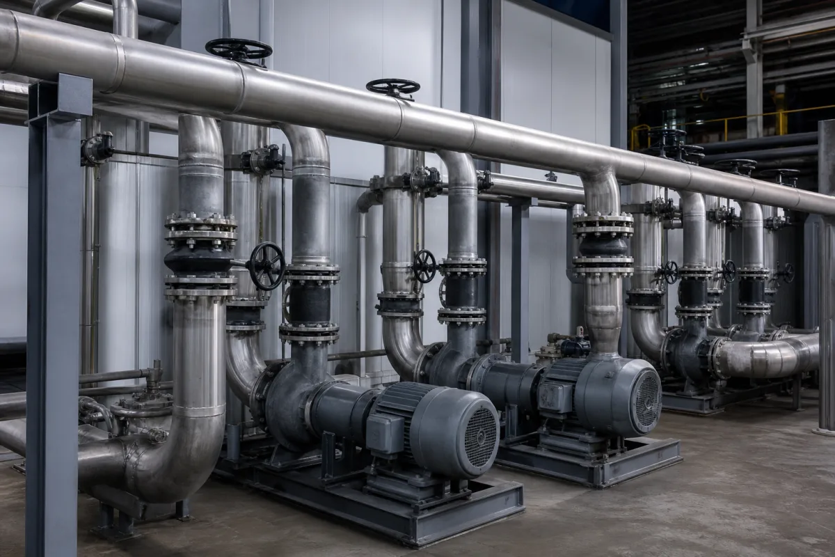
Representative product image. Confirm appearance and specifications with the manufacturer.

Product Specifications

Technical details and manufacturing context for Piping Network

Definition
The piping network is a critical component of the laminar cooling system, consisting of interconnected pipes, fittings, and valves that transport cooling fluid (typically water or specialized coolant) from the supply source to the cooling zones and back to the reservoir. It ensures uniform fluid distribution and controlled flow rates for precise temperature regulation in industrial processes. The network is designed to operate within specified parameters, including nominal diameters from DN50 to DN300 (ISO 6708), operating pressures of 1.0–1.6 MPa, and a test pressure of 2.4 MPa. Operating temperatures range from 0 to 60°C, with flow rates between 100 and 500 m³/h. Pressure loss is maintained between 0.05 and 0.15 MPa to ensure cooling efficiency. Pipe wall thickness varies from 3.0 to 8.0 mm (ISO 4200), and material grades include 304 to 316L stainless steel (ASTM A312), as well as carbon steel, PVC, and copper. Surface roughness is ≤0.8 μm Ra (ISO 4287), and weight ranges from 50 to 500 kg. Leakage rate is ≤0.01 mL/min, and corrosion resistance is verified by a salt spray test of ≥1000 hours (ASTM B117). These values are directory reference ranges and must be confirmed for the specific model and application with the legal manufacturer or supplier. The network's design, including pipe diameter, layout, and valve placement, determines flow distribution, pressure drops, and cooling efficiency across different sections of the laminar cooling system. Proper selection requires consideration of fluid properties, system pressure, temperature, and environmental factors. Verification of compliance with standards such as ISO 6708, ISO 4200, ASTM A312, ISO 4287, and ASTM B117 should be requested from the supplier. Maintenance signals include pressure loss exceeding specified limits, visible corrosion, or leakage. Failure boundaries are defined by operating conditions outside the specified ranges, which may lead to thermal expansion, seal degradation, or structural failure.
Working Principle
The piping network operates by creating a closed-loop or open-loop fluid pathway where cooling fluid is pumped through pipes under controlled pressure. The network's design, including pipe diameter, layout, and valve placement, determines flow distribution, pressure drops, and cooling efficiency across different sections of the laminar cooling system. Fluid is delivered from the supply source to cooling zones and returned to the reservoir, ensuring uniform distribution and controlled flow rates. The system relies on pumps to maintain pressure and valves to regulate flow. Proper sizing and material selection are critical to avoid excessive pressure loss and ensure effective cooling. The network must be operated within specified temperature and pressure ranges to prevent thermal expansion and seal degradation. Regular monitoring of pressure, flow, and leakage is necessary to detect issues early. The system's performance is influenced by the physical properties of the fluid, pipe roughness, and the layout of the network. Verification of design parameters and compliance with standards is essential for reliable operation.
Common Materials
Stainless Steel, Carbon Steel, PVC, Copper
Technical Parameters
ParameterTypical rangeNotes & selection driver
Nominal DiameterDN50–DN300 mmDetermines flow capacity and compatibility with pumps and valves.ISO 6708
Operating Pressure1.0–1.6 MPa
Test Pressure2.4 MPaHydrostatic test pressure for shell integrity.
Operating Temperature0–60 °CAbove 60°C may cause thermal expansion and seal degradation.
Flow Rate100–500 m³/hRequired for effective cooling of laminar flow.
Pressure Loss0.05–0.15 MPaExcessive loss reduces cooling efficiency.
Pipe Wall Thickness3.0–8.0 mmThicker wall for higher pressure ratings.ISO 4200
Material Grade304–316L316L for corrosion resistance in cooling water.ASTM A312
Surface Roughness≤0.8 μm RaSmooth surface reduces fouling and pressure drop.ISO 4287
Weight50–500 kgAffects installation and support requirements.
Leakage Rate≤0.01 mL/minEnsures no fluid loss in closed loop.
Corrosion Resistance≥1000 hSalt spray test duration without pitting.ASTM B117

Ranges are indicative industry figures for RFQ preparation, not a supplier commitment. Confirm every value and standard with the legal manufacturer before ordering.

Components / BOM
  • Straight Pipes Part
    Primary conduits for fluid transport between system components
    Material: Stainless Steel
  • Pipe Fittings Part
    Connect pipes, change direction, or modify flow characteristics (elbows, tees, reducers)
    Material: Carbon Steel
  • Valves
    Control, regulate, or isolate fluid flow within the network
    Material: Brass/Stainless Steel
  • Pipe Supports/Hangers Part
    Secure and stabilize the piping network, preventing vibration and stress
    Material: Steel
  • Flanges and Gaskets Part
    Create sealed connections between pipe sections and system components
    Material: Steel/Rubber

Applied To / Applications

This component is essential for the following industrial systems and equipment:

Industrial Ecosystem & Supply Chain Structure

Complementary Systems
Downstream Applications
Specialized Tooling

Application Fit & Sizing Matrix

Operational Limits
pressure: 0 to 10 bar (g)
flow rate: Up to 500 m³/h
temperature: -20°C to 120°C
slurry concentration: Up to 30% solids by weight
Media Compatibility
✓ Water-glycol mixtures ✓ Industrial cooling oils ✓ Corrosion-inhibited water
Unsuitable: Highly corrosive acids (e.g., hydrochloric acid, sulfuric acid)
Sizing Data Required
  • Required cooling capacity (kW)
  • System pressure drop allowance (bar)
  • Fluid viscosity and density at operating temperature

Reliability & Engineering Risk Analysis

Failure Mode & Root Cause
Corrosion under insulation (CUI)
Cause: Moisture ingress beneath insulation leading to localized corrosion, often accelerated by chloride presence or acidic conditions.
Fatigue cracking at welded joints
Cause: Cyclic stresses from thermal expansion/contraction, vibration, or pressure fluctuations, exacerbated by poor weld geometry or residual stresses.
Maintenance Indicators
  • Visible leaks or weeping at flanges, valves, or fittings
  • Abnormal vibration or audible hammering (water hammer) in the system
Engineering Tips
  • Implement a comprehensive corrosion under insulation (CUI) management program, including regular insulation inspection and removal at high-risk areas.
  • Design and maintain proper pipe supports and expansion loops to manage thermal stresses, and use fatigue-resistant welding procedures for critical joints.

Indicative industry ranges for design and RFQ preparation. Confirm the exact figures and applicable standard with the manufacturer before specifying.

Compliance & Manufacturing Standards

Applicable Standards
ANSI/ASME B31.3 - Process Piping DIN EN 10204 - Metallic Products Types of Inspection Documents

Quoted from the published standard.

Manufacturing Precision
  • Wall Thickness: +/-10% of nominal thickness
  • Outer Diameter: +/-1% of nominal diameter
Quality Inspection
  • Hydrostatic Pressure Test
  • Visual and Dimensional Inspection

Manufacturers of Piping Network

Manufacturer profiles associated with Piping Network.

Sourcing Piping Network from China?
Tell us your specification and target quantity — we will match it against manufacturer records and come back with the factories that fit.
Request manufacturers We manufacture this

Manufacturer listings support early research and capability understanding. They are not certification, ranking, or transaction guarantees.

Technical documentation
Request current drawings, revision history, and a signed specification sheet.
Manufacturing capability
Verify equipment lists, process limits, capacity, and representative production evidence.
Inspection readiness
Confirm test methods, calibrated equipment, sampling plans, and traceable reports.
Supplier transparency
Check the legal entity, factory address, ownership, certifications, and direct contacts.

CNFX does not score or rank suppliers. Buyers must verify all claims and documents with the legal manufacturer before ordering.

Supply Chain Compatible Machinery & Devices

Automated Powder Coating System

Integrated industrial system for applying dry powder coatings to metal substrates.

Explore Specs →
Centrifugal Pump Impeller

The centrifugal pump impeller is a critical rotating component that converts mechanical energy from the motor into kinetic energy in fluid systems.

Explore Specs →
High-Precision CNC Laser Cutting Machine

Computer-controlled industrial machine using focused laser beams to cut sheet metal with micron-level accuracy.

Explore Specs →
Industrial-Grade Hydraulic Cylinder Piston Rod

This industrial-grade piston rod is a precision-ground cylindrical component designed for use in hydraulic cylinders.

Explore Specs →

Frequently Asked Questions

What materials are available for the piping network?

The piping network can be made from stainless steel (grades 304 to 316L), carbon steel, PVC, or copper. The material grade affects corrosion resistance and suitability for the cooling fluid. Confirm the specific material grade with the supplier for your application.

What is the operating pressure range?

The operating pressure is specified as 1.0 to 1.6 MPa, with a test pressure of 2.4 MPa. These values are reference ranges; verify the exact ratings for your model with the manufacturer.

How is the piping network tested for leakage?

The leakage rate is specified as ≤0.01 mL/min, tested. This ensures no fluid loss in a closed loop. Request test certificates from the supplier to confirm compliance.

What maintenance signals indicate a problem?

Signs of trouble include increased pressure loss beyond the specified 0.05–0.15 MPa, visible corrosion, or leakage. Also monitor for temperature excursions above 60°C, which can cause thermal expansion and seal degradation.

Data Basis

Editorial classification, named public sources where available, and source-reviewed manufacturer records.

Preliminary Technical Classification
This page supports structured research, RFQ preparation, and supplier evaluation. It does not replace buyer-led supplier qualification, standards review, or technical approval.
Buyer enquiry

Request manufacturing insight for Piping Network

Ask for use case, specification boundaries, supplier type, and RFQ preparation information for this product.

Where it goes
Straight to the CNFX editorial desk, and to the manufacturer if this product is linked to a claimed profile. Nothing is broadcast to a supplier list.
Your details stay here
We do not sell or rent enquiry data, and we do not add you to a mailing list. Used only to answer this request.
No commission, no middleman
CNFX is a directory. We take no cut of any order and never negotiate on a supplier's behalf.
What we don't claim
A listing is not an endorsement. Qualify every supplier and verify every figure yourself before ordering.

Your business information is used only to process this request.

Thank you! Your message has been sent. We'll respond within 1–3 business days.
Sorry, we couldn't send your message. Please try again, or email us at contact@cnfx.com.

Need to Manufacture Piping Network?

Compare manufacturer profiles with relevant product and process capability.

Previous Product
Pipe Layer
Next Product
Piston & Rod (Ram)
Get QuotesChat